The 20–30 minutes that EIS provides are diagnosis time, not protection time. If this signal opens the rack contactor directly, the benefit of early detection is cancelled out by nuisance shutdowns.
Conclusion. BMS analog front-end (AFE) chips with built-in electrochemical impedance spectroscopy (EIS) are entering ESS sites. According to a May 4, 2026 report by THE ELEC, Samsung SDI is reviewing the adoption of the AFE chip “ABS8210” from Korean startup Anabatic Semi (simultaneous measurement of 20 series cells, 120V high-voltage design with 150V extension in progress, built-in EIS, produced by SK keyfoundry, mass-production target November 2026), while SK On has already developed an EIS BMS based on an ADI chip with Hunate.
Texas Instruments (TI) also unveiled the “BQ79826Z-Q1” on June 10, 2026, supporting up to 26 cells per device, with voltage accuracy better than 2mV across the full -40°C to 125°C range, EIS measurement 5 times faster than before, and ISO 26262 ASIL-D. The benefit the articles share is that thermal runaway is detected 20–30 minutes earlier than with conventional threshold alarms. The conclusion from an electrical design standpoint is this — use the EIS signal as a pre-alarm layer placed in front of the existing voltage and temperature threshold protection, and limit the response to reversible actions such as charge-current limiting (derating), stronger cooling and shorter monitoring intervals.
Rack contactor opening and fire-suppression release remain, as before, the job of threshold protection and hardware interlocks, and EIS software judgment must not replace or bypass that path.
Some background. Inside a BMS, the AFE is the eyes and ears that convert cell voltage, current and temperature signals into digital data, and the MCU is the brain that issues charge and discharge control commands from that data. The AFE market has been split between ADI and TI, and if Samsung SDI puts the Anabatic Semi chip into ESS, it will be the first case of implementing EIS with a domestically made chip.
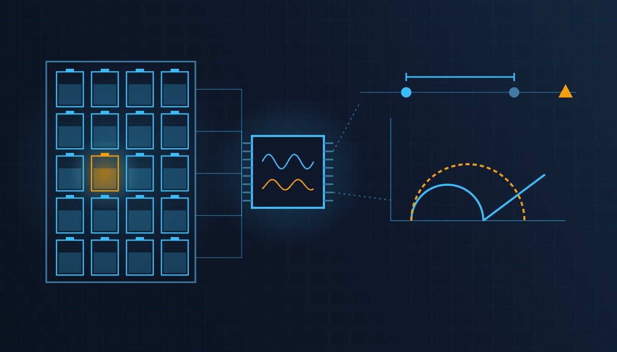
The article likens EIS to a blood test — whereas a conventional BMS sounds an alarm when voltage or temperature crosses a threshold, EIS injects a small current into the cell and reads the change in internal resistance to diagnose the state of each individual cell at an earlier stage. The bidding motive is also clear.
Among the non-price evaluation items of the ESS central contract market, the score for “contribution to the domestic ESS industry ecosystem” rose from 9.6 points in round 1 to 12.5 points in round 2, and Samsung SDI, having secured 56% (3.8GWh) of total volume ordered across rounds 1 and 2, will deliver its container-integrated SBB 1.5 to the domestic central contract market this October.
There is one counterintuitive observation from the field. Once an early-detection function arrives, the temptation is to trip interlocks “sooner and harder,” but the design actually has to go the other way. EIS impedance deviation is a statistical signal that shifts with cell chemistry, temperature and state of charge (SOC), so it is not as deterministic as threshold protection. Tie contactor opening directly to this signal and you gain none of the 20–30 minutes, only more unnecessary rack trips. The value of early detection lies not in “stopping sooner” but in “buying time to recover without stopping.”
Premise (based on the operating time chart): T0 EIS impedance deviation exceeds the pre-alarm threshold → T0 + a few seconds: charge-current derating and stronger-cooling commands → T0 + a few minutes: pre-alarm resets automatically if the deviation clears / shortened monitoring interval is maintained if it does not → T1 (around T0 + 20–30 minutes per the articles) voltage/temperature threshold alarm → T2 rack contactor opens (existing protection) → T3 fire suppression releases (existing fire interlock). The absolute EIS threshold value, the magnitude and frequency of the excitation current, and the measured distribution of the T0–T1 interval appear in none of the articles, so they are items to verify, and the logic below covers only the pre-alarm layer in the T0–T1 window.
Safety Interlock Verification Order (Top Priority)
- Confirm the hardware protection path is independent — Overvoltage, overtemperature and overcurrent hardware trips and the EMO (Emergency Off) circuit must operate regardless of EIS software judgment, and no output of the EIS logic may delay, block or bypass this path.
- Grade separation — Separate the output contacts themselves: EIS pre-alarm is diagnostic grade (only reversible actions allowed), threshold alarm is protection grade (contactor opening and fire suppression allowed). Do not mix the two grades on the same relay or the same DO.
- Check measurement interference — Confirm that the EIS excitation signal is isolated or time-multiplexed from the existing protective voltage measurement channels. If the excitation signal rides onto the protection channels as noise, threshold protection may misoperate or become desensitized. The actual effect can only be established by waveform analysis and field measurement.
- Fail-safe on communication loss — If the AFE-MCU daisy-chain communication is lost, drop the EIS pre-alarm into an “unable to judge” state and let protection grade continue to operate on the existing hardware thresholds. Logic that interprets communication loss as “no abnormality” is prohibited.
- State reset conditions explicitly — The pre-alarm resets automatically only when the deviation stays below the reset value for a set time, and re-closing after contactor opening requires a manual reset as before.
EIS Pre-Alarm Layer I/O Map
| Signal | I/O address | Type | Operating condition |
|---|---|---|---|
| Cell voltage (20ch) | AI601 | Analog In (V) | Existing threshold protection input, channel separated from EIS |
| Cell temperature | AI602 | Analog In (°C) | Existing threshold protection input |
| EIS impedance deviation | AI603 | Analog In (%) | Deviation from reference curve, pre-alarm decision value |
| EIS phase angle | AI604 | Analog In (deg) | Supports deviation decision, never used alone |
| AFE communication status | DI601 | Digital In | If OFF, switch to EIS unable-to-judge state |
| Hardware overtemperature trip | DI602 | Digital In (Read-Only) | Protection grade, no intervention by this logic |
| Charge-current limit command | AO601 | Analog Out (A) | Derating command to PCS on pre-alarm |
| Stronger-cooling command | DO601 | Digital Out | ON on pre-alarm, delayed OFF on clear |
| EIS pre-alarm | DO602 | Digital Out | Diagnostic-grade contact, for HMI/EMS notification only |
| Rack contactor open | DO603 | Digital Out | Protection grade, ON only by threshold alarm or hardware trip |
The implication of this I/O map fits in one line. No matter how precise AI603 becomes, DO603 must stay tied only to AI601, AI602 and DI602, and only when that separation holds do EIS’s 20–30 minutes remain real response time rather than nuisance shutdowns.
PLC Logic Snippet (IEC 61131-3 Structured Text Pseudocode)
(* ESS rack EIS pre-alarm layer - diagnostic grade only, outputs separated from protection grade *)
(* CAUTION: DO603 contactor opening is driven only from the threshold protection / hardware trip path; this logic must not access it *)
(* AI603: EIS impedance deviation %, DI601: AFE communication status, AO601: charge-current limit command A *)

VAR
  AI603_EIS_DEV_PCT      : REAL;   (* impedance deviation from reference curve, % *)
  DI601_AFE_COMM_OK      : BOOL;   (* AFE daisy-chain communication healthy *)
  DI602_HW_OT_TRIP       : BOOL;   (* hardware overtemperature trip, read-only *)
  AO601_CHG_LIMIT_A      : REAL;   (* PCS charge-current limit command *)
  DO601_COOL_BOOST       : BOOL;
  DO602_EIS_PREALARM     : BOOL;
  EIS_DEV_THRESHOLD      : REAL := 15.0;   (* example value, verify by field measurement per cell chemistry and temperature *)
  EIS_DEV_RESET          : REAL := 8.0;    (* example value, hysteresis reset value *)
  CHG_LIMIT_NORMAL_A     : REAL := 200.0;  (* example value *)
  CHG_LIMIT_DERATE_A     : REAL := 50.0;   (* example value *)
  EIS_VALID              : BOOL;
  T_HOLD                 : TON;            (* timer confirming the deviation persists *)
  T_RESET                : TON;            (* timer confirming the reset persists *)
END_VAR

(* 1. Decision validity: on communication loss, unable to judge - never interpret as no abnormality *)
EIS_VALID := DI601_AFE_COMM_OK;

(* 2. Persistence check: do not raise pre-alarm on a momentary deviation (example 3000ms) *)
T_HOLD(IN := EIS_VALID AND (AI603_EIS_DEV_PCT > EIS_DEV_THRESHOLD), PT := T#3000ms);
T_RESET(IN := EIS_VALID AND (AI603_EIS_DEV_PCT < EIS_DEV_RESET), PT := T#60000ms);

(* 3. Pre-alarm latch: SET on persistent exceedance, RESET when held below reset value for 60s *)
IF T_HOLD.Q THEN
  DO602_EIS_PREALARM := TRUE;
ELSIF T_RESET.Q THEN
  DO602_EIS_PREALARM := FALSE;
END_IF;

(* 4. Only reversible responses allowed: derating + stronger cooling *)
IF DO602_EIS_PREALARM THEN
  AO601_CHG_LIMIT_A := CHG_LIMIT_DERATE_A;
  DO601_COOL_BOOST := TRUE;
ELSE
  AO601_CHG_LIMIT_A := CHG_LIMIT_NORMAL_A;
  DO601_COOL_BOOST := FALSE;
END_IF;

(* 5. When unable to judge, report whether the pre-alarm is held via HMI display; protection grade keeps running on existing hardware thresholds *)
(* DI602_HW_OT_TRIP and DO603 contactor opening are read-only / not accessed in this logic - no branch of any kind *)
Boundary Conditions — Handling Field Variables
The point where this design’s advantage flips is the threshold value. EIS impedance reference curves themselves shift with cell chemistry (NCA, LFP), temperature, SOC and aging state, so operating with a fixed threshold produces frequent false alarms in the summer heat or in low-SOC ranges, and operators get into the habit of ignoring the pre-alarm. In that case, the 20–30 minutes of early detection effectively do not exist. The reference curve must be set by measuring the initial EIS spectrum of the installed cells, and the noise effect of the excitation current on the protection channels can likewise only be established by waveform analysis and field measurement. In addition, mass production of the Anabatic Semi chip in November 2026 and its adoption by Samsung SDI were at the plan and review stage as of the articles, so actual application is an item to verify.
References
THE ELEC, “Samsung SDI pushes to localize battery management chips for ESS” (2026-05-04, in Korean)
Digital Daily, “‘Early detection of thermal runaway signs’… TI unveils battery monitor with integrated EIS engine” (2026-06-10, in Korean)
US10386422B2, Lithium Balance AS, “Electrochemical impedance spectroscopy in battery management systems” — priority date 2014-07-25, granted 2019-08-20, legal status Active, anticipated expiration 2035-07-17 (per Google Patents lookup). It claims a BMS method that applies excitation signals in two frequency bands to a battery, calculates impedance from the ratio to the response, and compares it with a circuit model to determine SoH and SoC. Because it does not claim thermal runaway determination itself, it is cited only as prior art for on-board EIS measurement.