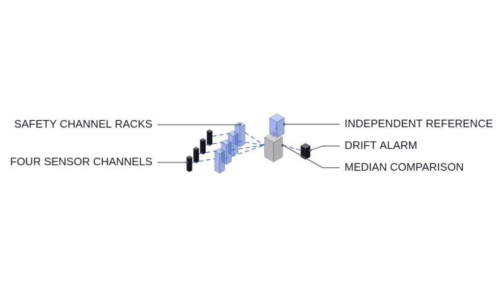
The short answer first. In a four-channel, 2-out-of-4 reactor protection system (RPS), the real design decision is not the voting ratio. It is what you do with a channel once it is pulled from service: bypass it, or leave it in the tripped state. Bypass it and the logic becomes 2-out-of-3, so the trip function survives a single failure. Leave it tripped and the logic becomes 1-out-of-3, so one spurious signal from any remaining channel shuts the reactor down. Unless that choice, together with a “no two channels bypassed at once” interlock, is fixed in hardware first, the benefit of four channels disappears every time a channel goes into maintenance.
Start with the safety interlock conditions
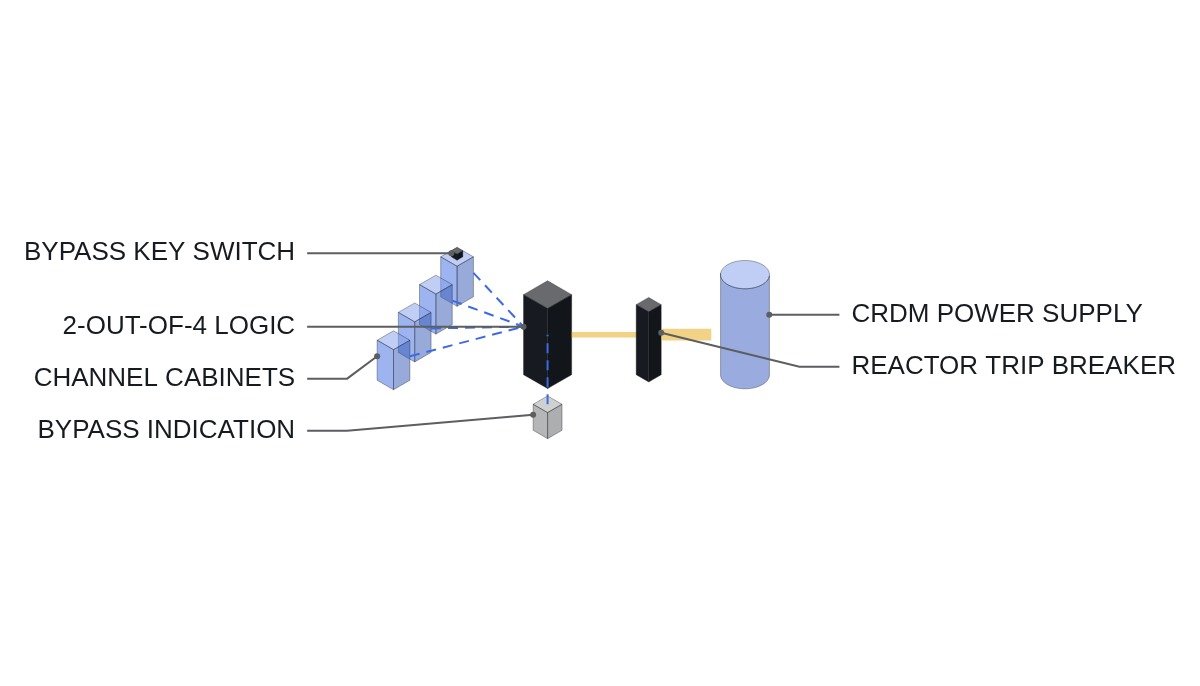
Before discussing the logic, pin down the premise. A reactor trip must work in the de-energize-to-trip direction: the undervoltage coils of the reactor trip breakers (RTB) drop out, so loss of power or loss of signal produces a trip. The code below is pseudocode to explain the coincidence conditions; the actual trip path is built on a qualified safety-grade platform and hardwired circuits.
- □ Confirm each channel’s bistable output is energized in normal operation and de-energized on trip. Loss of channel power must equal a channel trip.
- □ Confirm the manual trip switch opens the RTB coil circuit directly, without passing through the logic processor. Manual trip must not depend on a software path.
- □ Confirm one channel bypass switch per channel, key-operated, with hardwired mutual exclusion so that two channels cannot be bypassed at once.
- □ Confirm the bypass state is automatically and continuously indicated in the control room. An unindicated bypass is not an acceptable design.
- □ Confirm channel power, cabling, and installation areas are physically separated (independence per IEEE 384).
What 2-out-of-4 prevents, and what it allows
Coincidence logic exists to handle two failure types at once: failure to trip when a trip is needed, and spurious trip when it is not. Requiring two of four channels means that if one channel fails silent, two of the remaining three still produce the trip, and if one channel sends a false signal, it cannot trip the plant on its own.
The problem is maintenance and calibration. The moment you take a channel out for testing, four channels become three, and the remaining logic defines the plant state. Bypass the channel and the logic reconfigures to 2-out-of-3, keeping both single-failure tolerance and spurious-trip margin. Leave the channel tripped and the logic becomes 1-out-of-3: more conservative on the failure-to-trip side, but with zero margin against a spurious trip.
IEEE 603 requires safety systems to keep performing under a single failure, and bypasses during test and maintenance have to fit inside that principle. That is why most four-channel designs default to “one channel bypass allowed, simultaneous two-channel bypass prohibited.”
Logic transition sequence during channel maintenance
- Select the channel for maintenance and confirm from control room indication that no other channel is bypassed.
- Operate the channel bypass key switch. Hardwired mutual exclusion physically blocks bypass inputs from the other channels.
- The logic processor receives the bypass input, removes the channel from the vote, and reconfigures to 2-out-of-3.
- Confirm the bypass indicator and alarm appear in the control room.
- After channel test and calibration, confirm the bistable is in its normal (energized) state, then remove the bypass.
- Confirm the logic has returned to 2-out-of-4 and the bypass indication has cleared.
Coincidence logic pseudocode (IEC 61131-3 ST)
(* I/O MAP - per-channel bistable and bypass inputs *)
(* %I0.0 : DI_CH_A_NOT_TRIP  - channel A normal (energized)=1, trip or power loss=0 *)
(* %I0.1 : DI_CH_B_NOT_TRIP *)
(* %I0.2 : DI_CH_C_NOT_TRIP *)
(* %I0.3 : DI_CH_D_NOT_TRIP *)
(* %I1.0 : DI_CH_A_BYPASS    - key switch, signal after hardwired mutual exclusion *)
(* %I1.1 : DI_CH_B_BYPASS *)
(* %I1.2 : DI_CH_C_BYPASS *)
(* %I1.3 : DI_CH_D_BYPASS *)
(* %Q0.0 : DO_RTB_UV_HOLD    - 1=hold RTB undervoltage coil energized, 0=trip *)
(* %Q0.1 : DO_BYPASS_ALARM   - control room bypass indication *)
(* %Q0.2 : DO_DOUBLE_BYPASS_FAULT *)

(* 1. Effective trip per channel - bypassed channels are removed from the vote *)
X_TRIP_A := NOT DI_CH_A_NOT_TRIP AND NOT DI_CH_A_BYPASS;
X_TRIP_B := NOT DI_CH_B_NOT_TRIP AND NOT DI_CH_B_BYPASS;
X_TRIP_C := NOT DI_CH_C_NOT_TRIP AND NOT DI_CH_C_BYPASS;
X_TRIP_D := NOT DI_CH_D_NOT_TRIP AND NOT DI_CH_D_BYPASS;

N_TRIP   := BOOL_TO_INT(X_TRIP_A) + BOOL_TO_INT(X_TRIP_B)
          + BOOL_TO_INT(X_TRIP_C) + BOOL_TO_INT(X_TRIP_D);
N_BYPASS := BOOL_TO_INT(DI_CH_A_BYPASS) + BOOL_TO_INT(DI_CH_B_BYPASS)
          + BOOL_TO_INT(DI_CH_C_BYPASS) + BOOL_TO_INT(DI_CH_D_BYPASS);

(* 2. 0 bypassed: 2/4, 1 bypassed: 2/3 - either way, trip on 2 or more *)
(* 3. 2+ bypassed must be blocked in hardware; if detected, go conservative (trip) *)
IF N_BYPASS >= 2 THEN
    DO_DOUBLE_BYPASS_FAULT := TRUE;
    DO_RTB_UV_HOLD         := FALSE;   (* conservative: trip *)
ELSIF N_TRIP >= 2 THEN
    DO_RTB_UV_HOLD         := FALSE;   (* coincidence met: trip *)
ELSE
    DO_RTB_UV_HOLD         := TRUE;
END_IF;

DO_BYPASS_ALARM := (N_BYPASS >= 1);
(* Note: the manual trip switch opens the RTB coil circuit directly, bypassing this logic *)
The branch to watch is item 3. Simultaneous two-channel bypass is supposed to be prevented at the source by hardwired mutual exclusion; detection in the logic is only a second line of defense for when that hardware fails. A design that treats the second line as the first is not acceptable.
Bypass versus tripped-state comparison
| Item | Normal | 1 ch bypassed | 1 ch tripped |
|---|---|---|---|
| Effective logic | 2/4 | 2/3 | 1/3 |
| Fail-to-trip margin | Up to 2 failed ch | Up to 1 failed ch | Up to 2 failed ch |
| Spurious-trip margin | Up to 1 false signal | Up to 1 false signal | None |
| Single-failure criterion | Met | Met | Met (trip direction) |
| Operating impact | None | Indication, alarm | Higher spurious-trip risk |
Read this table along the spurious-trip row. Both approaches satisfy the single-failure criterion on the fail-to-trip side, so for channels with short, repetitive maintenance windows, bypass is the better choice for plant availability. The tripped-state approach is best kept as the conservative option when the bypass hardware itself cannot be trusted, or when a failed channel cannot be restored for a long time.
Where field practice slips
Four channels mean something only when the channels are independent. If all four share a power panel, a cable tray, or a software version, a single common cause failure (CCF) can drive all four wrong in the same direction, and the vote filters nothing. That is why digital RPS designs also call for diversity, such as a trip signal based on a different principle or a separate diverse protection system on a different platform.
The other point is confirming bypass removal. If a channel is left bypassed after calibration, the plant keeps running on 2-out-of-3. The single-failure criterion still holds, but the moment someone tries to maintain another channel, either the mutual exclusion blocks them or, if the exclusion has failed, two channels end up bypassed. In practice, the bypass state belongs on the shift turnover checklist.
Boundary conditions
This judgment fails under two conditions. First, if the bypass hardware (key switches, mutual exclusion relays, indication circuits) has no monitoring of its own failure modes, bypass can produce an invisible two-channel bypass, and the tripped-state approach becomes the safer choice. Second, if channel independence is not assured, the difference between 2/4 and 2/3 is meaningless, and common cause failure countermeasures come before any logic choice.
The single decision rule: choose one-channel bypass (2/3) only when the bypass state itself is monitored, indicated, and mutually excluded in hardwired circuits; otherwise, leave the channel under maintenance in the tripped state.