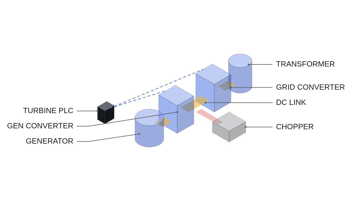
Bottom line first. In a full-converter wind turbine, what actually limits FRT (Fault Ride-Through, low-voltage ride-through) performance is often not the reactive current control algorithm but the energy budget the DC-link chopper resistor can absorb. A single voltage dip passes as designed. But when dips repeat at short intervals, as in a failed auto-reclose, the chopper resistor hits its thermal limit on the second dip. So the FRT sequence needs the remaining chopper energy budget as an interlock input alongside the voltage condition, and a branch that cuts generator-side torque and pitch earlier when the budget runs short.
Safety interlock: what must hold before FRT
FRT is the function of staying connected through a grid fault, but equipment protection still comes first while riding through. FRT logic must never be written so that it suppresses equipment protection.
- □ Confirm that DC-link overvoltage protection blocks the IGBT gates through a hardware comparator independent of the converter controller. Entering FRT mode must not mask this protection.
- □ Nacelle emergency stop and overspeed protection run through a hardwired safety chain that performs emergency pitch feathering and opens the main breaker. The PLC and converter controller receive the chain status as monitoring inputs only.
- □ Confirm the path by which chopper resistor overtemperature protection (thermistor or thermal model) blocks the chopper gate. Once the chopper is blocked there is nothing left to protect the DC link, so abandoning FRT and moving to a stop sequence is the correct behavior.
- □ Confirm that the grid-side converter current limit and the reactive current injection command do not conflict. In reactive-current-priority mode, active current headroom shrinks.
- □ Put the response-time difference between the generator-side torque reduction command and the pitch controller on a timing chart.
Where the energy goes during FRT
When grid voltage drops, the active power the grid-side converter can export falls in proportion to voltage. Meanwhile the rotor keeps turning at the same speed because of inertia and aerodynamic torque, and the generator-side converter keeps pushing power into the DC link. The difference between power in and power out charges the DC-link capacitor, and once the voltage crosses the chopper threshold, the chopper burns the energy in a resistor.
The magnitude can be estimated with simple multiplication. Assumption: a 3 MW generator at rated output, grid voltage near zero for 0.5 s, and no generator-side torque reduction during that time. The chopper then absorbs 3 MW × 0.5 s = 1.5 MJ. If generator-side torque is cut quickly right after the dip, this number shrinks substantially and the difference is stored as rotor kinetic energy. In other words, control decides how the energy is split between the chopper and rotor inertia.
The problem is repeated dips. When auto-reclose closes back onto a line fault, a second dip arrives a few hundred milliseconds to a few seconds later. The chopper resistor has a small thermal mass and a long cooling time constant, so the second dose of energy arrives before the temperature from the first dip has come down. If design verification covered only a single dip, the chopper overtemperature protection trips under this condition and the turbine drops off.
| Item | DFIG | Full converter (PMSG etc.) |
|---|---|---|
| Energy absorber | Crowbar, DC chopper | DC chopper |
| Generator-grid link | Stator direct | Fully decoupled by converter |
| Reactive current in dip | Limited when crowbar fires | Injected by grid-side converter |
| Repeated-dip bottleneck | Crowbar, rotor-side current | Chopper thermal capacity |
| Key interlock input | Rotor current, DC voltage | DC voltage, chopper energy |
The table says one thing. A full converter fully decouples the generator from the grid, which makes FRT control easier, but all surplus energy converges on one place: the DC chopper. That is why full-converter FRT interlocks center on chopper energy management rather than on tracking a voltage curve.
FRT sequence and chopper energy budget logic
The assumed timing chart: at t0 grid voltage falls below the FRT entry threshold. Right after t0 the grid-side converter switches to reactive-current-priority mode. The generator side receives a torque reduction command. The chopper fires in hardware at its DC voltage threshold. When voltage rises above the recovery threshold, active power ramps back. The code below covers only the part handled by the upper-level turbine controller (PLC).
(* I/O MAP - TURBINE CONTROLLER, FRT SUPERVISION *)
(* %I1.0  DI_SAFETY_CHAIN_OK   : NACELLE E-STOP / OVERSPEED CHAIN (MONITOR ONLY) *)
(* %I1.1  DI_CHOP_OT_TRIP      : CHOPPER RESISTOR OVERTEMP TRIP (HARDWARE) *)
(* %I1.2  DI_CONV_FRT_ACTIVE   : CONVERTER REPORTS FRT MODE *)
(* %IW200 AI_V_GRID_PU         : GRID VOLTAGE, PU x1000 *)
(* %IW202 AI_P_CHOPPER_KW      : CHOPPER POWER ESTIMATE (kW), FROM CONVERTER VIA PROFINET *)
(* %IW204 AI_T_CHOP_RES        : CHOPPER RESISTOR TEMP (degC) *)
(* %QW300 AO_TORQUE_LIMIT_PCT  : GENERATOR TORQUE LIMIT (%) *)
(* %QW302 AO_PITCH_RATE_REQ    : PITCH RATE REQUEST TO PITCH SYSTEM *)
(* %Q1.0  DO_FRT_ABORT_STOP    : REQUEST CONTROLLED STOP *)

(* 1. CHOPPER ENERGY BUDGET - INTEGRATE POWER, DECAY WITH COOLING TIME CONSTANT *)
(* SCAN TIME T_SCAN_S, EXAMPLE 0.01 s *)
R_E_CHOP_KJ := R_E_CHOP_KJ + AI_P_CHOPPER_KW * T_SCAN_S
               - R_E_CHOP_KJ * T_SCAN_S / R_TAU_COOL_S;
R_E_BUDGET_KJ := R_E_CHOP_MAX_KJ - R_E_CHOP_KJ;

(* 2. EARLY TORQUE CUT WHEN REMAINING BUDGET CANNOT COVER ANOTHER DIP *)
(* R_E_ONE_DIP_KJ = ENERGY OF ONE DESIGN DIP WITH NORMAL TORQUE CUT *)
B_BUDGET_LOW := R_E_BUDGET_KJ < R_E_ONE_DIP_KJ;

IF DI_CONV_FRT_ACTIVE THEN
    IF B_BUDGET_LOW THEN
        AO_TORQUE_LIMIT_PCT := I_TORQUE_LIM_DEEP;   (* DEEPER CUT, ENERGY INTO ROTOR *)
        AO_PITCH_RATE_REQ   := I_PITCH_RATE_FAST;   (* REDUCE AERO POWER *)
    ELSE
        AO_TORQUE_LIMIT_PCT := I_TORQUE_LIM_NORMAL;
        AO_PITCH_RATE_REQ   := I_PITCH_RATE_NORMAL;
    END_IF;
END_IF;

(* 3. ABORT FRT - CHOPPER TRIPPED OR SAFETY CHAIN OPEN *)
IF DI_CHOP_OT_TRIP OR NOT DI_SAFETY_CHAIN_OK THEN
    DO_FRT_ABORT_STOP := TRUE;    (* CONTROLLED STOP; HARDWARE OVP STAYS INDEPENDENT *)
END_IF;
R_TAU_COOL_S, R_E_CHOP_MAX_KJ and R_E_ONE_DIP_KJ come from the chopper resistor’s thermal capacity and cooling conditions and must be set from manufacturer data and measurement. The first-order thermal model used here is for explanation only; how accurately it tracks actual resistor temperature requires waveform analysis and field measurement.
Commissioning checklist
- □ Beyond the single-dip test, record chopper temperature rise under consecutive dips that reproduce the design reclose interval. Check whether the type test report covers only a single dip.
- □ Record symmetrical and asymmetrical dips separately. In asymmetrical dips the negative-sequence component puts a double-frequency ripple on the DC-link voltage, which changes the chopper’s firing pattern.
- □ Record rotor speed rise during the dip and check the margin to the overspeed setting. The deeper the torque cut, the more energy goes into the rotor and the smaller this margin becomes.
- □ Confirm that the active power recovery ramp after voltage returns is within the grid operator’s required range.
- □ Cross-check measurements against the voltage dip test procedure of the IEC 61400-21 series and the FRT curve of the applicable grid code.
Boundary conditions: when this design is wrong
First, if the chopper is oversized so that it can comfortably absorb the total energy of consecutive dips, the energy budget logic is unnecessary. That judgment can only be made by comparing the chopper resistor rating against the total energy of the consecutive-dip scenario.
Second, on turbine models with little overspeed margin, the deep-torque-cut branch can itself cause an overspeed trip. In that case the weight has to shift toward reducing aerodynamic power with pitch instead of the chopper, but pitch responds more slowly than the chopper and does not help with the first dip.
Third, when the grid operator requires active current to be maintained during the dip. The grid-side converter then exports some active power, which reduces the chopper burden, but reactive current headroom within the current limit shrinks. Check the requirement against the original grid code text.
The single decision rule: if the total energy of consecutive dips in the design reclose scenario does not fit within the chopper resistor’s thermal limit, add the chopper energy budget to the FRT interlock and include an early torque and pitch reduction branch.