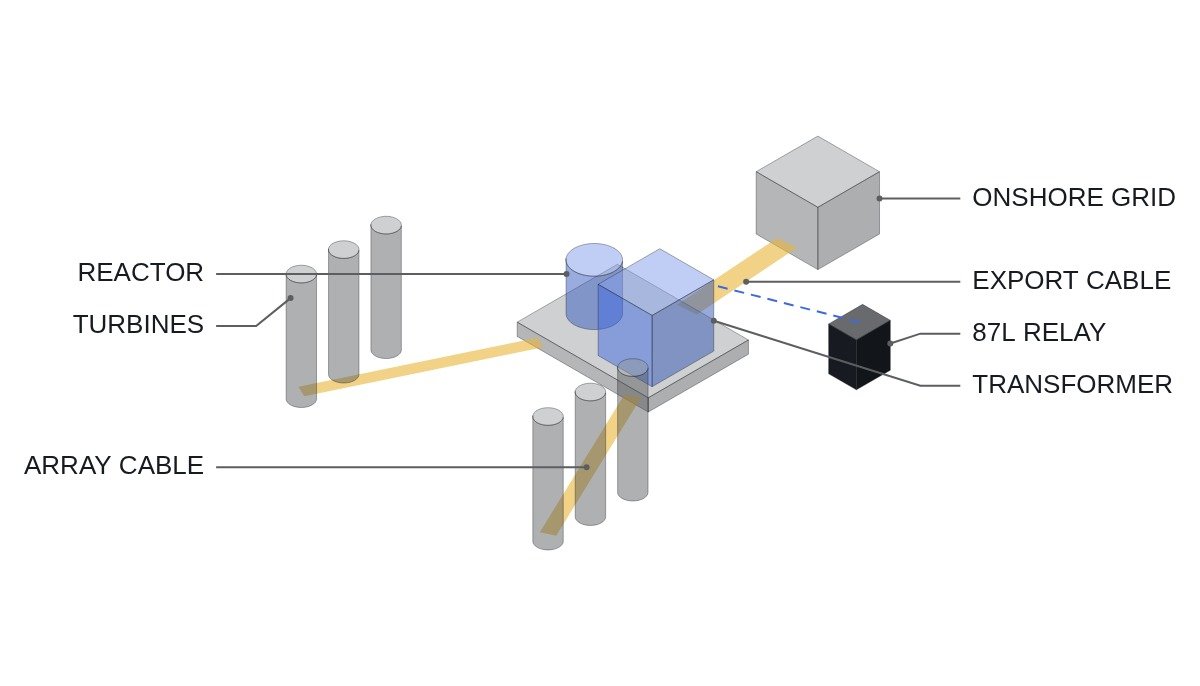
Bottom line first. If protection for an offshore wind farm’s array cables, export cable and offshore substation transformer is built around overcurrent relays, selectivity breaks down under the condition where almost no fault current comes from the plant side. Wind turbine converters limit their current during faults to around rated, so most of the fault current seen offshore arrives from the onshore grid through the export cable. The reference arrangement is therefore to make differential relays (87L, 87T) the main protection, deal first with long-cable charging current and transformer inrush as sources of maloperation, and tie the energization sequence itself into interlocks.
Safety interlock: offshore substation close and open conditions
An offshore substation normally runs unmanned and access is weather-limited. The recovery cost of a single wrong closing operation is therefore far higher than onshore. Lock down the energization interlocks before working on protection coordination.
- □ Offshore substation fire and gas detection and emergency stop open the affected bay breakers through hardwired circuits and block reclosing. The bay controller monitors this state and rejects remote close commands; it never clears it in software.
- □ When energizing the export cable, confirm that the shunt reactor is connected. Energizing a long AC cable without compensation raises the receiving-end voltage (Ferranti effect).
- □ Before closing the transformer, confirm the secondary (array-side) breaker is open. No-load energization keeps the inrush condition simple.
- □ Before closing an array string breaker, confirm that every turbine on that string is stopped and disconnected.
- □ Check the mechanical and electrical interlock between the earthing switch (ES) and the main breaker. Because remote operation is the norm, the status inputs to the electrical interlock must be cross-verified with two contacts (a and b).
Protection coordination when fault current comes from one side
Onshore plant protection rests on the assumption that fault current is large and its direction is clear. For offshore wind that assumption is only half true. When an array cable faults, the onshore grid supplies a large current through the export cable and transformer, but the turbines on the same string add only a small current because of converter current limiting. The string breaker’s overcurrent element operates, but there is no means to tell which section of the string failed. Array strings are usually isolated as a whole string, and locating the section is left to a later procedure.
The export cable is different. With differential relays (87L) at both ends, internal faults can be selected regardless of current magnitude. The problem is charging current. AC cables have high capacitance, so even in steady state there is a current difference between the two ends, and to the differential element this looks like an internal fault. You either use charging current compensation or raise the minimum pickup above the charging current, and the latter costs sensitivity to high-resistance earth faults.
The magnitude of charging current can be estimated with a formula. Assumption: with phase voltage U, cable capacitance per km C, length L and frequency f, the per-phase charging current is I = 2πf × C × L × U. It is proportional to length, so the farther the site is from shore, the more differential settings and reactor compensation grow into a combined problem. Use the manufacturer’s test report value for the actual cable capacitance.
| Section | Main protection | Maloperation cause | Countermeasure |
|---|---|---|---|
| Array string | Overcurrent, earth fault | Small turbine contribution | Isolate whole string |
| Offshore transformer | 87T differential | Inrush current | 2nd harmonic restraint |
| Export cable | 87L differential | Charging current | Charging current compensation |
| Shunt reactor | Differential, overcurrent | Switching transients | Fixed energization order |
| Breaker failure | 50BF | Communication delay | Parallel hardwired trip |
The third column is the core. In offshore wind protection, maloperation becomes a problem before failure to operate, because currents that disturb differential elements during normal operation (charging current and inrush) are structurally large. Verify settings under energization conditions before verifying them under fault conditions.
Energization sequence interlock logic (bay controller)
The assumed timing chart: step 1, confirm the shunt reactor breaker is closed. Step 2, energize the export cable from the onshore end. Step 3, close the offshore transformer primary breaker (secondary open). Step 4, after inrush decays, close array string breakers one by one. A voltage check sits between each step. Status is exchanged over IEC61850_GOOSE, but trip paths run in parallel over hardwiring.
(* I/O MAP - OFFSHORE SUBSTATION BAY CONTROLLER *)
(* %I3.0  DI_OSS_SAFETY_OK      : FIRE/GAS/E-STOP HARDWIRED CHAIN (MONITOR ONLY) *)
(* %I3.1  DI_SR_CB_CLOSED_A     : SHUNT REACTOR CB AUX a *)
(* %I3.2  DI_SR_CB_OPEN_B       : SHUNT REACTOR CB AUX b *)
(* %I3.3  DI_TX_HV_CB_CLOSED    : TRANSFORMER HV CB CLOSED *)
(* %I3.4  DI_TX_LV_CB_OPEN      : TRANSFORMER LV CB OPEN *)
(* %I3.5  DI_ES_OPEN            : EARTHING SWITCH OPEN *)
(* %I3.6  DI_GOOSE_87L_HEALTHY  : 87L RELAY HEALTHY VIA IEC61850_GOOSE *)
(* %IW500 AI_V_EXPORT_PU        : EXPORT CABLE VOLTAGE (PU x1000) *)
(* %IW502 AI_I_2H_RATIO         : TX 2ND HARMONIC RATIO (% x10) *)
(* %Q3.0  DO_TX_HV_CLOSE_PERMIT : TRANSFORMER HV CB CLOSE PERMIT *)
(* %Q3.1  DO_TX_LV_CLOSE_PERMIT : TRANSFORMER LV CB CLOSE PERMIT *)
(* %Q3.2  DO_STRING_CLOSE_PERMIT: ARRAY STRING CB CLOSE PERMIT (SEQUENTIAL) *)

(* 1. REACTOR STATUS - BOTH AUX CONTACTS MUST AGREE *)
B_SR_IN_SERVICE := DI_SR_CB_CLOSED_A AND NOT DI_SR_CB_OPEN_B;
B_SR_DISAGREE   := DI_SR_CB_CLOSED_A = DI_SR_CB_OPEN_B;   (* ALARM, BLOCK ALL CLOSE *)

(* 2. TRANSFORMER HV CLOSE - CABLE ENERGISED, REACTOR IN, LV OPEN, ES OPEN *)
DO_TX_HV_CLOSE_PERMIT := DI_OSS_SAFETY_OK AND B_SR_IN_SERVICE AND NOT B_SR_DISAGREE
                         AND DI_TX_LV_CB_OPEN AND DI_ES_OPEN
                         AND (AI_V_EXPORT_PU > I_V_MIN_PU) AND (AI_V_EXPORT_PU < I_V_MAX_PU)
                         AND DI_GOOSE_87L_HEALTHY;

(* 3. LV CLOSE - WAIT UNTIL INRUSH DECAYS (2ND HARMONIC BELOW THRESHOLD) *)
TON_INRUSH(IN := DI_TX_HV_CB_CLOSED AND (AI_I_2H_RATIO < I_2H_SETTLED), PT := T_INRUSH_HOLD);
DO_TX_LV_CLOSE_PERMIT := DI_OSS_SAFETY_OK AND TON_INRUSH.Q;

(* 4. STRINGS ONE AT A TIME - NEXT PERMIT ONLY AFTER PREVIOUS STRING STABLE *)
DO_STRING_CLOSE_PERMIT := DO_TX_LV_CLOSE_PERMIT AND B_PREV_STRING_STABLE
                          AND NOT B_STRING_CLOSING;

(* 5. 87L COMMUNICATION LOSS - BLOCK NEW CLOSE, BACKUP PROTECTION STAYS ACTIVE *)
IF NOT DI_GOOSE_87L_HEALTHY THEN
    DO_TX_HV_CLOSE_PERMIT := FALSE;
END_IF;
I_V_MIN_PU, I_V_MAX_PU, I_2H_SETTLED and T_INRUSH_HOLD are example names. If 87L communication is lost, differential protection is gone and distance and overcurrent backup protection remain. New closing operations are blocked in that state, but whether to stop equipment already running is a matter for agreement with the grid operator. GOOSE message latency and loss rate depend on the site network, so they are left as items that require waveform analysis and field measurement.
Design review checklist
- □ Calculate export cable charging current from length and capacitance, and review the 87L minimum pickup together with the charging current compensation setting.
- □ Calculate shunt reactor rating and cable no-load voltage rise for each energization order. Confirm that energizing without the reactor is blocked by the close interlock.
- □ Check 87T second-harmonic restraint settings under transformer inrush. When several large transformers are energized in succession, check for sympathetic inrush.
- □ Obtain the turbine converters’ fault current contribution characteristics (magnitude, duration, whether reactive current is injected) as a manufacturer model and feed them into the coordination study. Cross-check the model against the model definitions of the IEC 61400-27 series.
- □ Specify relay functional requirements per the IEC 60255 series and substation communication per IEC 61850 in the specification.
Boundary conditions: when this arrangement changes
First, if the export link is HVDC, the charging current and Ferranti issues in this article disappear, and the center of protection moves to DC-side fault clearing at the converter stations. Do not use the same checklist as for AC export.
Second, for a site close to shore with small cable charging current, the 87L minimum pickup can stay low, and energization without a reactor may be possible. Make that judgment only from the calculated charging current.
Third, if turbine converters run in grid-forming mode, their current contribution during faults changes. Leaving the existing settings unchanged means you cannot know whether they will maloperate or fail to operate, so protection coordination has to be recalculated.
The single decision rule: if most of the offshore fault current comes from the onshore grid, make differential rather than overcurrent the main protection, and control charging current and inrush first through energization sequence interlocks.