The conclusion first. Starting January 1, 2026, the Ministry of Climate, Energy and Environment made participation in an inverter specification survey mandatory for solar power producers with installed capacity of 500kW or more, with a compliance deadline of the end of 2026. The core of this measure is strengthening high voltage ride-through (HVRT) performance, which has nothing to do with curtailment. It does not replace the existing low voltage ride-through (LVRT) or low/high frequency ride-through (LFRT/HFRT) logic; it adds a new interlock layer on top of them. Producers of 500kW or more should use the remaining time to confirm their inverter manufacturer, model and date of manufacture, and manage the software upgrade schedule separately from LVRT.
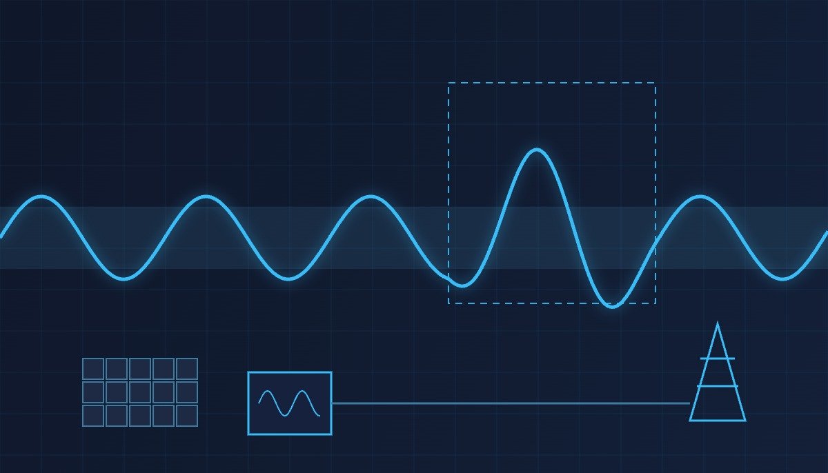
HVRT is not a sub-option of LVRT but an independent interlock. If the two logics are tied to a single voltage monitoring register, the ride-through decision can be delayed in the overvoltage zone.
E2News reported on December 17, 2025 that the Ministry of Climate, Energy and Environment planned to issue an order, effective January 1, 2026, requiring solar power producers of 500kW or more to respond to and participate in an inverter specification survey led by the Korea Power Exchange and KEPCO. The government explained that the measure is “entirely unrelated to curtailment, and is a function that allows generating facilities to keep running stably for a certain period even when voltage and frequency fluctuations occur on the grid,” with a compliance deadline of the end of 2026.
According to an earlier report on September 30, 2025, the authorities had been pursuing LFRT, HFRT and LVRT performance improvements since 2020, but HVRT, already in use overseas, had been left out of that work, making a new round of measures unavoidable. Overvoltage during light-load hours has been observed not infrequently on parts of the grid in the Honam region, where recent renewable installations have concentrated, and the overvoltage also observed during the April 2025 blackout in Spain has added to the sense of urgency.
Separately, starting June 1, 2026, the Korea Power Exchange requires new solar, wind, fuel cell and energy storage operators connected to the transmission grid (22.9kV dedicated lines and 154kV and above) to submit a field performance test report within 6 months of first energization.
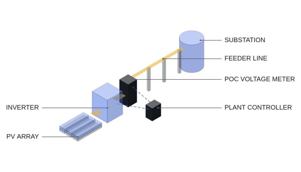
Precondition: the exact HVRT setting adjustment procedure for each inverter manufacturer and model has not been published, so the checklist below is developed for a typical configuration in which a grid-connected solar inverter processes LVRT, HVRT and LFRT/HFRT ride-through logic in the same voltage and frequency monitoring circuit. In actual application, it must be replaced and confirmed against the time chart in the inverter manufacturer’s specifications and the original text of the revised grid interconnection standards issued by KEPCO and the Korea Power Exchange.
Safety interlock check order (top priority)
- LVRT (low voltage ride-through) interlock — when grid voltage is detected at 80% of rated or below, the inverter does not disconnect immediately but injects reactive current to help voltage recover, and switches from reactive to active current on recovery (a zone already applied since 2023)
- HVRT (high voltage ride-through) interlock — the subject of this order; even when grid voltage exceeds the upper limit, the inverter does not trip immediately but keeps running for a set time, with software settings adjusted separately (the exact voltage limit and hold time need to be confirmed from each manufacturer’s compliance result)
- LFRT/HFRT (low/high frequency ride-through) interlock — keeps running for a set time even outside the 59.5-60.5Hz range; existing logic applied since 2020 and subject to a separate recheck apart from this order
- MPPT (maximum power point tracking) stop interlock — stops MPPT on entering any of the ride-through modes above so that reactive current is injected first, preventing overcurrent trips caused by increased active current
- Grid separation protection (anti-islanding) — if voltage or frequency abnormality continues beyond the ride-through hold time, the inverter is finally disconnected from the grid. This final separation function must be maintained through hardware protective relay and breaker interlocking regardless of software setting adjustments; designs that replace or bypass it with software logic alone are not covered on this site.
Grid voltage ride-through I/O map
| Signal | I/O address | Type | Operating condition |
|---|---|---|---|
| Grid voltage detection | AI201 | Analog In 4-20mA | Continuous monitoring against rated voltage; LVRT mode at 80% or below |
| Grid voltage upper limit exceeded | DI201 | Digital In | 1 = HVRT set upper limit exceeded → enter ride-through mode (limit value to be confirmed from manufacturer’s compliance result) |
| Grid frequency | AI202 | Analog In 4-20mA | 59.5-60.5Hz; LFRT/HFRT mode when outside |
| MPPT stop command | DO201 | Digital Out | 1 (stop) on entering LVRT or HVRT mode, 0 on return to normal |
| Inverter reactive current command | AO201 | Analog Out | Reactive current output takes priority during ride-through mode; switches to active current after voltage recovers |
| Grid separation trip | DO202 | Digital Out | When the ride-through hold time is exceeded, cut-off through hardware protective relay interlocking (final stage) |
The implication of this checklist is clear. If DI201 (HVRT upper limit exceeded) and the existing LVRT monitoring logic are processed with the same voltage register priority, the ride-through mode decision can get tangled in grid disturbances where overvoltage and undervoltage occur in quick succession. Producers of 500kW or more should confirm, when upgrading inverter software, that LVRT and HVRT logic are each implemented as independent conditional branches.
PLC logic snippet (IEC 61131-3 Structured Text pseudocode)
(* Solar inverter ride-through logic - independent LVRT/HVRT branches *)
(* AI201: detected grid voltage (%), DI201: HVRT upper limit exceeded signal, AI202: grid frequency *)
IF AI201 <= 80.0 THEN
  DO201 := 1; (* stop MPPT *)
  AO201 := AO201_LVRT_REF; (* LVRT reactive current command *)
ELSIF DI201 = 1 THEN
  DO201 := 1; (* stop MPPT; HVRT upper limit to be confirmed from manufacturer's compliance result *)
  AO201 := AO201_HVRT_REF; (* HVRT reactive current command *)
ELSIF (AI202 < 59.5) OR (AI202 > 60.5) THEN
  DO201 := 1; (* LFRT/HFRT mode *)
ELSE
  DO201 := 0; (* normal operation, resume MPPT *)
  AO201 := AO201_MPPT_REF;
END_IF;
(* When the ride-through hold time is exceeded, the hardware protective relay performs the final cut-off via DO202 *)
Boundary conditions — handling field variables
The HVRT voltage upper limit and ride-through hold time that will actually apply in Korea have not been finalized, pending the specification survey and the progress of the measures, so this requires waveform analysis and field measurement. The government has also said it plans to extend the scope to facilities below 500kW if necessary, but no specific implementation date has been confirmed. The selection criterion comes down to one question: when planning the inverter software upgrade, did you treat LVRT and HVRT as the same interlock, or separate them into distinct layers?
References
- E2News, “Ministry of Climate orders HVRT and specification survey for solar inverters of 500kW or more” (2025-12-17)
- E2News, “HVRT and LFRT performance improvement to start with solar inverters of 500kW or more” (2025-09-30)
- Korea Power Exchange, “Notice on changes to renewable power plant electricity trading from June 2026” (notice of 2026-05-13)
- KR101529982B1 — Korea Energy Co., Ltd. (original applicant: Cheongju University Industry-Academic Cooperation Foundation), Low-voltage grid connection maintenance system for grid-connected solar inverters (Google Patents)