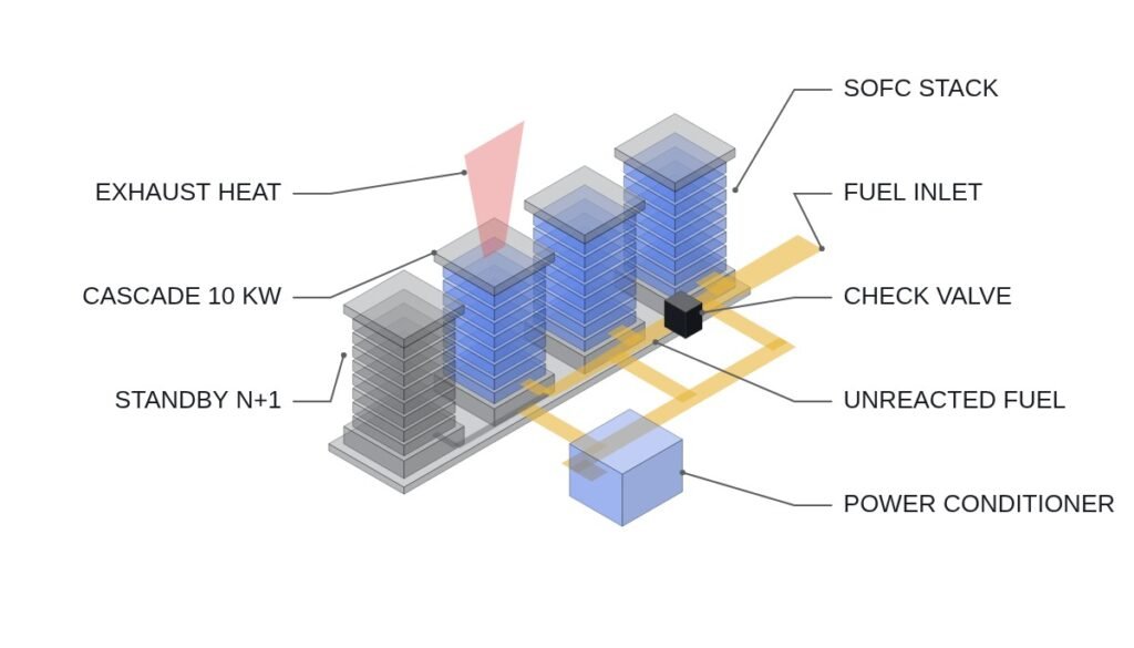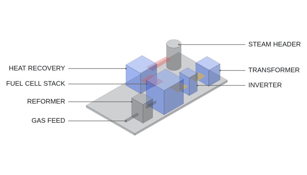
Let me start with the conclusion. Solid oxide fuel cells (SOFC) operate at high temperatures of 650–950°C and can convert natural gas or hydrogen directly into electricity near a data center, which is why they are drawing attention as an on-site power source for sites that cannot wait for an external grid connection. But treating SOFC only as a detour around grid delays misses something. If heating-rate control by the heating element and the reactant purge sequence are not completed first during stack startup, the ceramic electrolyte can be damaged, so an aggressive initial startup timed to the data center’s go-live schedule is constrained from the interlock design stage onward.
The bottleneck of SOFC on-site generation is not fuel procurement but the startup heat-up sequence, and that sequence fundamentally conflicts with the data center’s demand for immediate operation.
In a report on May 20, 2026, Etoday said that Hansun Engineering, a company specializing in instrumentation fittings and valves, is ramping up sales to the hydrogen fuel cell market on the back of expanding AI data center investment in the United States. A company official said that “full-scale deliveries in the hydrogen segment began this year” and that “our U.S. customer keeps expanding its SOFC-based power capacity.” First-quarter revenue was KRW 22.3 billion, up about 70% year on year, and operating profit was KRW 6.2 billion, up about 269% over the same period.
The company participates as a supplier to a domestic SOFC manufacturer and produces plumbing modules, fittings and valves for hydrogen fuel cells, where high heat resistance and durability are required. According to the same article, U.S. SOFC company Bloom Energy is pursuing a fuel cell system project for AI data centers with global asset manager Brookfield and is expanding its production capacity. The surge in data center power demand is also observed in Korea, and global data center power demand in 2026 is projected at 133 GW, up 27% from the previous year.
Premise: the exact startup heat-up profiles and purge sequence specifications of individual SOFC system manufacturers have not been disclosed, so the checklist below is developed on the basis of a typical SOFC system configuration in which heating-element heat-up and reactant purge are sequentially interlocked to protect the stack. In actual application, it must be replaced and verified against the startup time chart in the system manufacturer’s specification.
Safety Interlock Verification Order (Top Priority)
- Reactant purge complete interlock — if residual air and fuel remain mixed inside the stack during startup or shutdown, local oxidation and reduction reactions can damage the electrodes, so opening of the fuel valve is blocked by interlock until completion of the inert-gas (nitrogen, etc.) purge is confirmed
- Stack heat-up ramp-rate interlock — if the temperature rise driven by the heating element exceeds the set upper limit, thermal stress develops in the ceramic electrolyte with a risk of cracking, so heating-element output is limited immediately when the ramp rate is exceeded (the specific upper limit in °C/min must be confirmed in the stack manufacturer’s specification)
- Fuel-air stoichiometric ratio interlock — if the air-to-fuel ratio leaves its set range during normal operation, there is a risk of stack overheating or oxidation damage, so load is reduced immediately
- Grid-parallel transfer interlock — the transfer sequence differs depending on whether the unit runs in parallel with the data center’s UPS and PDU or fully independently (off-grid), and the SOFC-side breaker opens when a parallel-system abnormality is detected
- EMO (Emergency Off) — when a fuel leak is detected at high-temperature piping or fittings, the principle is that a hardwired fail-safe solenoid valve cuts off the fuel supply directly; designs that replace or bypass this shutoff function with software logic alone are not covered on this site.
SOFC Startup Sequence I/O Map
| Signal | I/O address | Type | Operating condition |
|---|---|---|---|
| Stack temperature | AI301 | Analog In (thermocouple, 4-20mA converted) | Normal range 650–950°C; limit heating-element output if exceeded |
| Heating-element ramp rate | AO301 | Analog Out | PID control within the set upper limit (°C/min) (upper limit to be confirmed in manufacturer’s specification) |
| Purge complete status | DI301 | Digital In | 1 = inert-gas purge complete → fuel valve opening permitted |
| Fuel supply valve | DO301 | Digital Out | Opens only when DI301 = 1 and stack temperature is normal |
| Fuel:air ratio abnormal | DI302 | Digital In | 1 = stoichiometric ratio out of range → immediate load ramp-down via AO302 |
| Grid-parallel status | DI303 | Digital In | 1 = running in parallel with the data center system → transfer interlock active |
| Emergency fuel shutoff | DO302 | Digital Out | On leak detection or EMO, hardware solenoid valve cuts off directly (final stage) |
The implication of this checklist is clear. Until DI301 (purge complete) is confirmed, DO301 (fuel valve) must not open under any higher-level command, and a design that shortens or bypasses the purge sequence because the data center schedule is tight is a problem tied directly to stack life.
PLC Logic Snippet (IEC 61131-3 Structured Text Pseudocode)
(* SOFC stack startup interlock logic - purge, heat-up, fuel open in sequence *)
(* AI301: stack temperature, DI301: purge complete, DI302: fuel-air ratio abnormal, DI303: grid-parallel status *)
IF DI301 = 0 THEN
  DO301 := 0; (* purge not complete, fuel valve opening prohibited *)
ELSIF AI301 > STACK_TEMP_MAX THEN
  AO301 := 0.0; (* limit heating-element output *)
  DO301 := 0;
ELSIF DI302 = 1 THEN
  AO302 := AO302 - RAMP_DOWN_STEP; (* stoichiometric ratio abnormal, ramp down load *)
ELSE
  DO301 := 1; (* open fuel valve only when purge complete and temperature normal *)
END_IF;
(* On leak detection or EMO, DO302 is cut off separately by the hardware solenoid *)
Boundary Conditions — Handling Field Variables
SOFC on-site generation cases are currently being reported mainly around U.S. AI data centers. For application in Korea, domestic permitting standards for piping and valves, such as the High-Pressure Gas Safety Control Act, may apply separately in addition to KEPCO’s grid interconnection standards, so this requires waveform analysis and field measurement. Stack heat-up profiles and purge durations differ by manufacturer and capacity, so comparison against the specification must come first. The selection criterion condenses to one: whether to adopt SOFC on-site generation should be judged by asking “Is the grid-connection wait longer than the time needed to procure, install and prepare the SOFC for startup?”
References
- Etoday, “Hansun Engineering ramps up SOFC component supply for U.S. AI data center power infrastructure” (2026-05-20, in Korean)
- CIO, “Gartner: data center power consumption to rise 26% in 2026… AI servers account for 31%” (in Korean)
- KR102624449B1 — Wonik Materials Co., Ltd., Ammonia-based solid oxide fuel cell (SOFC) system with heat-up by a heating element and method of operating the same (Google Patents)