To state the conclusion first: an SOFC (solid oxide fuel cell) cascade configuration beats a single-stack configuration at stationary generation sites where load swings are large and part-load operating hours are long. Conversely, at a baseload-only site with steady load, the added complexity of the cascade’s power-conditioning interlocks can become a burden instead. The result announced by Bumhan Fuel Cell — that the 10㎾-class cascade SOFC system it developed under a national R&D project reached 60.8% electrical efficiency — should be read as a case that supports this distinction.
1. Background — why the cascade configuration is drawing attention
Bumhan Fuel Cell announced that, through a national project of the Korea Institute of Energy Technology Evaluation and Planning, it developed Korea’s first 10㎾-class cascade SOFC system. The system achieved 60.8% electrical efficiency, and it is being presented as a next-generation high-efficiency generation technology that could raise electrical efficiency to around 70% when combined with ceramic proton conductor technology.
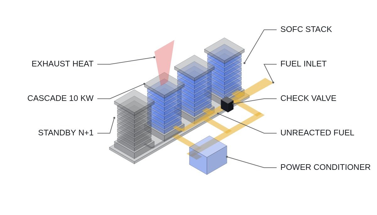
A cascade configuration arranges several stack modules in series and parallel so that the downstream stack reuses fuel that did not react in the upstream stack (unreacted fuel gas). Compared with building the full capacity from one large stack, it can raise fuel utilization — but it also adds power conditioning between stacks and more interlock logic, and that has to be stated alongside the efficiency gain.
2. Where it wins — sites with large load swings and frequent part-load operation
The current condition is this. At sites such as commercial-building CHP or data center backup power, where load varies widely by time of day and a long share of hours is spent at part load relative to rating, a single large stack suffers a sharp efficiency drop in the part-load range.
Applying a cascade configuration changes that as follows. The number of running stack modules can be adjusted to the load level (N+1 staging control), so each running stack operates close to its rated efficiency even in the part-load range. An operating strategy that keeps stopped modules in a warm standby state to shorten restart time is also possible.
The connecting logic is here. The larger the load swing, the larger the efficiency benefit of staging control, so at these sites there is more room to recover the up-front cost of cascade interlock design from improved operating efficiency.
3. Where it doesn’t — baseload-only sites with almost no load variation
The opposite condition is just as clear. At a baseload-only site running steadily at rated load 24 hours a day, the cascade’s advantage — part-load response — has no room to be used in the first place.
Applying a cascade configuration at such a site changes things as follows. Initial equipment cost and maintenance points rise together with the added inter-stack power conditioners, staging control logic and per-module interlock wiring. If load is steady, a single-stack configuration is better at reducing I/O point count and minimizing failure points.
4. Comparison table — by configuration
| Item | Cascade configuration | Single-stack configuration |
|---|---|---|
| Efficiency (part load) | Relatively better through staging control | Drops sharply at part load |
| Efficiency (rated, 10㎾ class) | 60.8% (Bumhan Fuel Cell demonstration value) | Varies by configuration and maker — check the datasheet |
| Interlock and control complexity | Per-module staging control required | Relatively simple |
| Suitable load pattern | Wide swings, frequent part load | Baseload only, steady load |
| Number of failure points | Grows in proportion to module count | Relatively few |
The row to watch in the table is “number of failure points.” As modules are added, the temperature and voltage monitoring points for each stack increase with them, so when choosing a cascade configuration, the efficiency gain has to be weighed against the maintenance burden from additional interlock and monitoring points.
5. Checklist for staging-control interlocks
- [ ] Confirm the load profile (kW by time of day) was obtained and the part-load operating share was calculated first
- [ ] Confirm the temperature and voltage monitoring points for each module are built as independent interlocks, and not tied into common wiring that becomes a single point of failure
- [ ] Confirm the start/stop priority of the staging logic (based on stack degradation) is documented
- [ ] Confirm a backflow-prevention interlock is provided on the piping that recycles unreacted fuel gas
- [ ] Confirm the logic isolates only the affected module, not the whole cascade, when a stack fault occurs (keep the principle that safety circuits such as EMO are never bypassed in software)
6. Boundary conditions and selection criterion
The point at which this judgment flips is clear. At a site where load is steady at baseload level and the part-load share is low, the cascade’s staging-control advantage has no room to show, and a simpler single-stack configuration is the rational choice for maintenance. Load swing width and part-load operating share — this single criterion is the current basis for choosing between the two configurations.