To state the conclusion first: a single-axis solar tracker turns the modules toward the sun to cut angle-of-incidence losses, and the gain shows up mainly in the morning and afternoon. A tracker should therefore be judged less on “how many percent more energy” and more on “which hours’ kWh it adds.” The size of the gain depends on the share of direct irradiance, so it shrinks in cloudy climates with a lot of diffuse light, and it brings the burden of drive maintenance and high-wind control. Trackers win on grids with frequent midday curtailment and high value for morning and afternoon power, on flat sites with strong direct sunlight.
Where It Wins, Where It Doesn’t
Under current conditions, a fixed array is tilted toward the south and produces an output peak around noon. In the morning and afternoon the sun is off the module’s face, so output falls even for the same irradiance. With no moving parts, the equipment is simple, and maintenance is mostly module cleaning and electrical inspection.
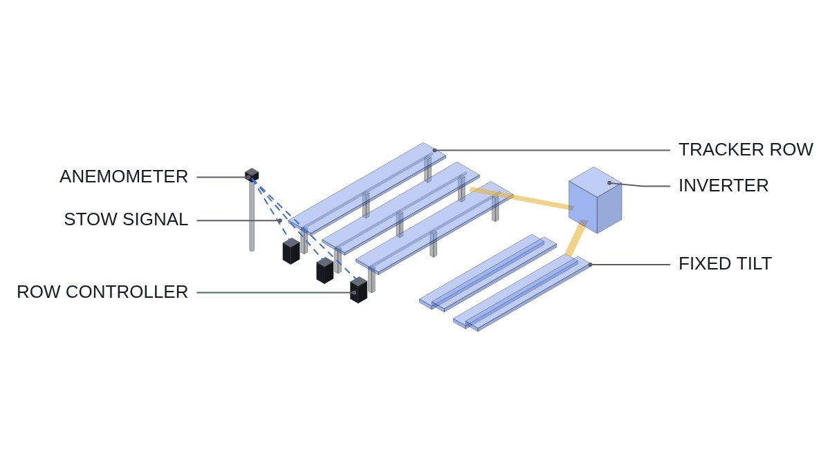
With a single-axis tracker, modules rotate on a north-south axis and follow the sun from east to west. Angle-of-incidence losses in the morning and afternoon fall, the shoulders of the output curve rise, and the peak becomes a broad plateau. In exchange, a control system of motors, drives, controllers, anemometers, and communications is spread across the whole array, and stowing to a safe angle in high winds becomes a mandatory function.
The connecting logic is this. A tracker is a generating plant with a control system bolted on, and the gain that control produces is concentrated in certain hours of the day. If power in those hours is valuable, the tracker creates more than its kWh gain; if it is not, or the gain itself is small, only the control system’s upkeep remains.
Calculating Incidence-Angle Loss, and the Limit Set by Diffuse Light
The direct component reaching the module surface equals direct normal irradiance (DNI) times the cosine of the angle of incidence. At 30°, cos 30° ≈ 0.866; at 60°, cos 60° = 0.5. Assumption: in the early morning a fixed module sees a 60° angle of incidence, and the tracker reduces it to 30°. The direct component then rises from 0.5 to 0.866, about 1.7 times. Near noon the fixed array’s angle is small too, so the difference almost disappears.
That calculation applies only to the direct component. Diffuse light scattered by cloud or haze arrives from the whole sky, so turning the module one way or another barely changes how much it receives. In climates with many overcast days and frequent haze, the diffuse share of irradiance rises and the tracker gain shrinks. A tracker study therefore needs separated direct and diffuse irradiance data, not just global irradiance.
Early morning and late afternoon bring another constraint. When the sun is low, turning modules fully toward it makes the front row shade the row behind. Trackers therefore deliberately roll back the angle in those hours, a control called backtracking, to avoid inter-row shading. Wider row spacing shortens the backtracking period but reduces the capacity that fits on the same land, so capacity per land area and tracker gain trade off against each other.
| Item | Fixed tilt | Single-axis tracker |
|---|---|---|
| Output curve | Noon peak | Higher morning/afternoon shoulders |
| Gain condition | N/A | High direct-irradiance share |
| Drives | None | Motors, drives, controllers |
| High-wind response | Handled by structure | Stow control required |
| Site conditions | Adapts easily to slopes | Favors flat, regular sites |
| Auxiliary power | Not needed | Needed for drives and comms |
Half of the cells on the tracker side are not gains but extra conditions. A tracker is a choice that buys energy together with responsibility for a control system’s reliability, and without an operating organization able to carry that responsibility, the gain does not last.
The Tracker as a Control System — Stow and Loss of Communication
The tracker function tied directly to safety is stow. When the anemometer signal exceeds the threshold, every row must move to an angle with low wind load. Three conditions need checking: when the wind signal is lost or reads abnormally, when communication between the master controller and row controllers drops, and when a grid outage removes drive power.
In all three cases the design must converge to a predefined safe state, not “hold last state.” A row controller that loses communication moves itself to stow, and drive power is backed by an auxiliary supply that can complete the stow motion during an outage. Leave out the sizing of that auxiliary supply and monitoring of its state of charge, and stow fails at the very moment it is needed.
Communication quality is also a variable. Row controllers spread across the array are linked by wireless or wired communication, and inverter switching noise or long cable runs can cause communication errors. Error frequency and cause require waveform analysis and field measurement after installation.
Clipping and Curtailment — Where the Tracker Gain Disappears
In designs with a high DC/AC ratio, even a fixed array hits the inverter rating at midday. A tracker also lifts midday output slightly, but that portion is clipped at the inverter and never becomes energy. The tracker’s real gain survives only in the morning and afternoon, below the inverter rating.
On grids with frequent midday curtailment, this structure actually works in the tracker’s favor. Midday output is limited anyway, and generation grows in the shoulder hours where there is no limit. For the same reason, in markets where midday prices are low and evening power is valuable, a tracker’s value per kWh exceeds that of a fixed array.
| Site and grid condition | Verdict |
|---|---|
| High direct share, flat site | Tracker favored |
| Frequent midday curtailment | Tracker favored (shoulder-hour value) |
| High diffuse share | Fixed favored |
| Sloped or irregular site | Fixed favored |
| Frequent high winds, remote unmanned site | Fixed favored |
In this table, the conditions favoring the tracker are irradiance and grid conditions, while those favoring fixed tilt are site and operating conditions. Even when the first two are met, if either of the last two applies, the tracker gain is cancelled by upkeep and outage risk.
Decision Sequence
- Obtain separated direct and diffuse irradiance data for the site.
- Check the grid’s curtailment history and the value of power by time of day.
- Confirm that site slope and shape suit tracker row layout.
- Calculate the actual extra energy after clipping, with the DC/AC ratio applied.
- Build the safe state and auxiliary power for each stow condition (abnormal wind signal, loss of communication, outage) into the design.
- Decide how drive maintenance staff and spare parts will be provided.
Boundary Conditions
The tracker advantage flips in climates with a high diffuse share, on sloped or irregular sites, on coasts with frequent high winds, and at remote sites hard for maintenance staff to reach. Under these conditions the incidence-angle gain is small, or rows stuck by drive failures eat into it. In designs with a high inverter loading ratio and long midday clipping, the tracker gain is also smaller than expected.
Conversely, the fixed-tilt advantage weakens on grids where midday curtailment is routine and morning and afternoon power is worth more than midday. There, even with similar total energy, the difference in generating hours turns into a difference in revenue.
The single decision criterion is this: choose a tracker only when direct irradiance dominates, morning and afternoon power is worth more than midday power on the grid, and the stow safe state can be guaranteed even under outage and loss-of-communication conditions.