Short answer first. In motor regenerative braking, what separates a braking resistor from a regenerative converter is not peak power but regenerated energy per hour (kWh) and the shape in which that energy arrives. On a horizontal transfer axis, where energy comes out in short bursts only during deceleration and cycles are far apart, the wasted energy is small and the braking resistor is simple and dependable. On hoists, lifts and unwinders, where energy comes out continuously while lowering or holding tension, the annual energy thrown away grows large enough that the extra cost of a regenerative converter can pay back. But a regenerative converter works only while the supply network accepts the energy, so the braking path during loss of supply has to be designed first.

Confirm the safety interlocks first
Handling regenerated energy is a question of whether braking works at all before it is a question of efficiency. If the energy cannot be absorbed, the drive trips on DC link overvoltage and the motor loses its braking force at that instant. Fix the following in hardware first.
- □ Braking resistor thermal switch: the temperature switch contact on the resistor is not an alarm. Wire it in series with the main contactor (KM1) coil circuit. If the brake chopper IGBT fails short, the resistor stays connected to the DC link and overheats. Drive software cannot disconnect it; only removing the supply works.
- □ Mechanical brake on vertical axes: fit a spring-applied, power-off brake, and interlock brake release with the drive’s torque-established condition. Electrical braking (regeneration or resistor) is not a holding means.
- □ Braking path on loss of supply: a regenerative converter on its own loses its regeneration path during a power failure. For vertical loads, combine it with a braking resistor or confirm the dynamic stopping performance of the mechanical brake.
- □ Resistor location and guarding: resistor surfaces run hot, so check clearance from combustibles, touch guards, and enclosure rating when mounted outside the panel.
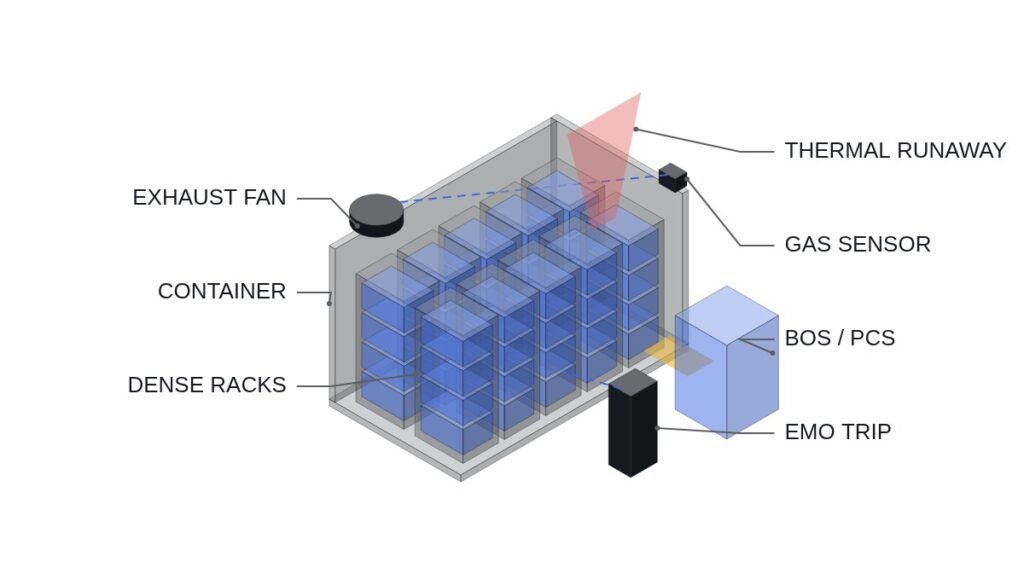
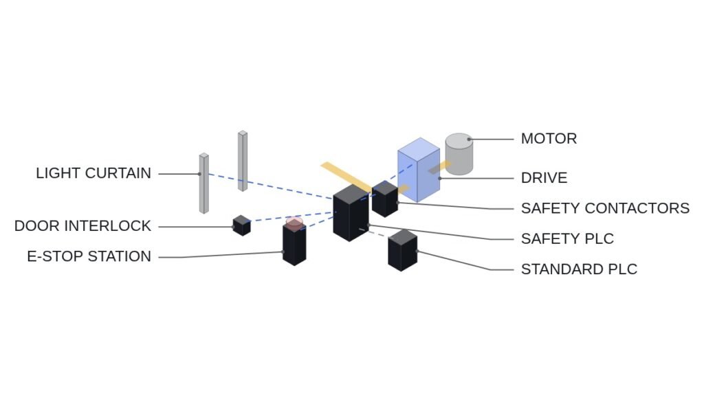
- □ EMO: the emergency stop and EMO are hardwired safety circuits that disconnect STO and KM1 directly. After disconnection, the mechanical brake must hold the load on vertical axes.
Regenerated energy: horizontal vs vertical axes
The deceleration energy of a horizontal rotating load is its kinetic energy, E = ½Jω². Assumptions: load-referred inertia J = 2 kg·m², speed 1,500 rpm, deceleration time 2 s, constant-torque deceleration, losses ignored (conservative for resistor sizing).
- ω = 2π × 1,500 / 60 = 157.1 rad/s
- E = ½ × 2 × 157.1² ≈ 24.7 kJ
- Braking torque T = Jω / t = 2 × 157.1 / 2 ≈ 157 N·m; peak power = Tω ≈ 24.7 kW (at the start of deceleration); average power ≈ 12.3 kW
- With a 20 s cycle (180 per hour), regenerated energy per hour = 24.7 kJ × 180 ≈ 4,440 kJ ≈ 1.23 kWh
Size the braking resistor with the drive’s braking threshold voltage VBR using R ≤ VBR² / Ppeak. Assumption: VBR = 750 V (confirm in the drive manual). R ≤ 750² / 24,700 ≈ 22.8 Ω, and it must also be at or above the drive’s minimum permitted resistance. Set the resistor’s continuous rating by checking the average power of about 1.23 kW against the permitted overload curve at the duty cycle (2 s / 20 s = 10%).
A vertical axis behaves differently. Assumptions: load 1,000 kg, lowering speed 0.5 m/s, lowering for 30 s. Regenerated power while lowering is P = mgv = 1,000 × 9.81 × 0.5 ≈ 4.9 kW, delivered continuously for 30 s, so one lowering stroke yields about 147 kJ. Peak power is about one fifth of the horizontal example, but the energy per stroke is about six times larger.
The judgement that follows from this comparison: on a horizontal axis, regenerated energy scales with the square of speed and bunches up at the moment of deceleration; on a vertical axis, it scales with lowering distance and accumulates over time. A braking resistor suits the first shape; a regenerative converter suits the second.
Comparison: braking resistor, regenerative converter, common DC bus
| Item | Braking resistor | Regen converter | Common DC bus |
|---|---|---|---|
| Energy handling | Burned as heat | Returned to the supply | Used as motoring power by other axes |
| On loss of supply | Keeps working (while DC link is live) | Cannot regenerate | Not possible without a motoring axis |
| Heat | Large, at the resistor | Conversion losses only | Small |
| Harmonics, grid impact | None | Needs review by converter type | None |
| Best-fit load | Intermittent decel, low inertia | Continuous regen, vertical and tension loads | Lines where motoring and regen overlap in time |
| Cost structure | Low capex, energy lost | High capex, energy recovered | Needs wiring and protection coordination design |
In this table, the “On loss of supply” row is the safety conclusion and the “Best-fit load” row is the economic conclusion. The plants where a regenerative converter pays off are mostly vertical loads, and the more vertical the load, the bigger the braking-path problem on loss of supply. That is why, on continuously regenerating vertical axes, a regenerative converter combined with a small braking resistor is often the sensible answer.
Monitoring logic: energy totalising and action before overheating
The PLC does not control the braking path. The braking resistor thermal trip and STO act through hardwiring. The PLC monitors DC link voltage and resistor temperature, asks for a longer deceleration ramp before a trip occurs, and totalises regenerated energy to leave a basis for the economic decision.
(* Regenerated energy monitoring and deceleration relief request - IEC 61131-3 ST *)
(* Braking resistor thermal switch -> in series with KM1 coil (hardwired); STO/EMO hardwired. Monitoring only *)
VAR
  DI_KM1_CLOSED           AT %I3.0  : BOOL;  (* Main contactor closed *)
  DI_BR_THERMO_TRIPPED    AT %I3.1  : BOOL;  (* Braking resistor thermal switch operated - monitoring only *)
  DI_MECH_BRAKE_RELEASED  AT %I3.2  : BOOL;  (* Mechanical brake released confirmation *)
  AI_DC_BUS_V             AT %IW120 : INT;   (* DC link voltage in V, drive monitor output *)
  AI_BR_RES_TEMP_C        AT %IW122 : INT;   (* Resistor surface temperature, thermocouple transmitter *)
  AI_BR_POWER_KW_X10      AT %IW124 : INT;   (* Braking power kW x10, mapped drive parameter *)
  DO_DECEL_EXTEND_REQ     AT %Q3.0  : BOOL;  (* Request longer decel -> switch drive parameter set *)
  DO_BR_TEMP_ALARM        AT %Q3.1  : BOOL;  (* Resistor high temperature alarm *)
  BR_ENERGY_WH                      : REAL;  (* Totalised regenerated energy, Wh *)
  SCAN_S                            : REAL := 0.01;  (* Assumed 10 ms scan time *)
  TEMP_WARN_C                       : INT := 150;    (* Assumed warning value, change to resistor spec *)
  VDC_WARN_V                        : INT := 720;    (* Assumed warning value, set below V_BR *)
END_VAR

(* Energy totalising: kW x10 -> W, integrated over scan time *)
IF DI_KM1_CLOSED THEN
  BR_ENERGY_WH := BR_ENERGY_WH + INT_TO_REAL(AI_BR_POWER_KW_X10) * 100.0 * SCAN_S / 3600.0;
END_IF;

(* Relief before trip: request longer deceleration on high resistor temperature or rising DC link voltage *)
DO_DECEL_EXTEND_REQ := (AI_BR_RES_TEMP_C > TEMP_WARN_C) OR (AI_DC_BUS_V > VDC_WARN_V);
DO_BR_TEMP_ALARM := (AI_BR_RES_TEMP_C > TEMP_WARN_C) OR DI_BR_THERMO_TRIPPED;

(* Caution: during vertical lowering, check per process that longer decel does not add lowering energy *)
Logging BR_ENERGY_WH monthly lets you decide on a regenerative converter from measured energy rather than estimates. Multiply the totalised value by the energy tariff to get the recoverable amount per year, and compare it with the extra cost of the regenerative converter. The accuracy of the braking power value reported by the drive varies by model, so cross-check by measuring resistor current separately if needed.
Boundary conditions
There are conditions under which this reasoning goes wrong. First, if the plant spends time running on a standby generator, the generator cannot accept the power a regenerative converter returns, which can cause reverse power protection or overspeed problems. In generator mode, a path that switches over to a braking resistor is needed. Second, if decelerating and accelerating axes on the same line overlap in time, sharing energy over a common DC bus is simpler than sending it back to the supply. In that case, input protection for each drive and DC-side fuse coordination must be redesigned. The single decision rule: choose a regenerative converter only when the annual energy value of the measured regenerated energy exceeds the converter’s extra cost within the payback period, and a separate braking path exists for loss of supply and generator operation.