Bottom line first. If distribution overcurrent (OCR) coordination is checked only at the maximum fault current, you miss curve crossings in the low-current region between relays with different curve types. Coordination has to be checked at both the maximum and the minimum fault current, and the curves must not meet anywhere in between. Ground overcurrent (OCGR) needs one more step of care: the magnitude of ground-fault current is set by the grounding method, and transformer winding connections block zero-sequence current, so it cannot be coordinated on the same chart as phase OCR.
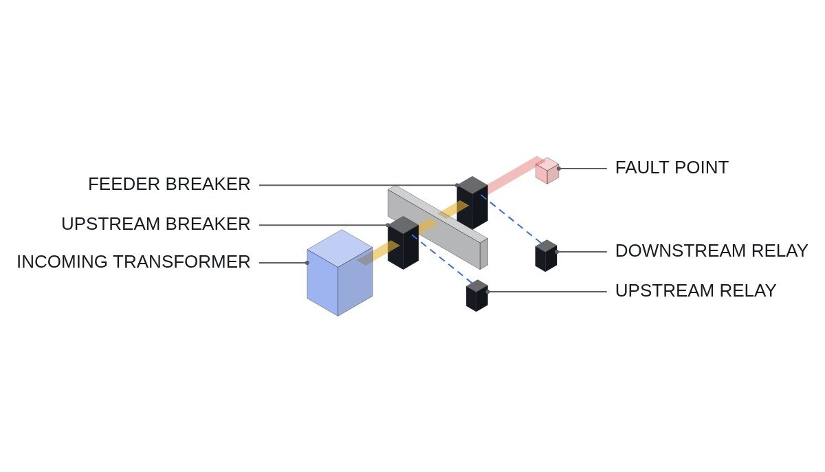
Safety interlocks first — the boundary between protective relays and the PLC
When a PLC appears in a protection coordination article, the first thing to settle is the boundary of roles. Protective relays trip; the PLC only monitors and grants close permissives.
- Protective relay trip outputs are hardwired directly to the breaker trip coil. No PLC or SCADA path is placed in the trip circuit.
- EMO is hardwired into the trip circuit; the PLC only reads its status.
- After a protection operation, the lockout relay (86) allows only local manual reset. It is not reset remotely or automatically by the PLC to reclose.
- With the earthing switch closed, the breaker closing circuit is blocked by hardwiring.
- Provide trip circuit supervision (TCS) and DC control supply monitoring. A breaker with a broken trip circuit will not operate no matter how well the curves coordinate.
- During setting changes, show the relay’s test status on SCADA and keep a record comparing settings before and after the work.
Inverse-time curves — same TMS, different shape
The inverse-time characteristics in IEC 60255-151 are as follows. M is the fault current as a multiple of pickup current, and TMS is the time multiplier setting.
- Standard inverse (SI): t = TMS × 0.14 / (M^0.02 − 1)
- Very inverse (VI): t = TMS × 13.5 / (M − 1)
- Extremely inverse (EI): t = TMS × 80 / (M² − 1)
| M (multiple) | SI | VI | EI |
|---|---|---|---|
| 2 | 1.00 s | 1.35 s | 2.67 s |
| 5 | 0.43 s | 0.34 s | 0.33 s |
| 10 | 0.30 s | 0.15 s | 0.08 s |
| 20 | 0.23 s | 0.07 s | 0.02 s |
Values are calculated at TMS 0.1. At M = 2, EI is the slowest; at M = 20, EI is the fastest. Two relays with different curve types can swap order somewhere, and the question is whether that point falls inside the range you are coordinating.
Worked example — right at maximum fault, wrong at minimum
Assumption: downstream feeder relay R2 has 400 A pickup, EI, TMS 0.2. Upstream relay R1 has 600 A pickup, SI, TMS 0.15. The coordination time interval (CTI) is 0.3 s. CTI combines relay timing error, breaker interrupting time and overshoot, and is set according to relay type and breaker specification.
- Maximum fault current 6,000 A: R2 at M = 15, t = 0.2 × 80 / 224 ≈ 0.071 s. R1 at M = 10, t = 0.15 × 0.14 / 0.0471 ≈ 0.446 s. A 0.37 s interval — coordinated.
- Minimum fault current 1,200 A: R2 at M = 3, t = 0.2 × 80 / 8 = 2.00 s. R1 at M = 2, t = 0.15 × 0.14 / 0.0140 ≈ 1.50 s. Upstream R1 operates first.
Checked only at maximum fault current, this design passes. There are two ways to correct it. Raising R1’s TMS requires R1 ≥ 2.30 s at the minimum fault current, so TMS ≥ 2.30 / 10.03 ≈ 0.23, and R1 then slows to about 0.68 s at maximum fault current. Switching R1 to EI as well can do the opposite and erase the margin at the maximum-current end (with the same pickup, setting TMS 0.09 gives R1 ≈ 0.073 s at 6,000 A, almost equal to R2), so both ends have to be recalculated. Either way the conclusion is the same: coordination that has not been calculated at both points is not coordination.
Treat OCGR separately
The ground-fault current seen by OCGR is set by the system grounding method. In a solidly grounded system it approaches phase-fault magnitude, but in a resistance-grounded system the resistor limits it, so OCGR pickup must be well below that limit. The current axis itself covers a different range from OCR.
In addition, a delta-wye transformer does not pass zero-sequence current. A secondary ground fault is invisible to the primary OCGR, so ground coordination is broken at the transformer and built separately on each side. Residually connected OCGR can misoperate on unbalanced secondary current during transformer magnetizing inrush or CT saturation; whether a core-balance CT or residual connection is more stable at a given installation requires waveform analysis and field measurement.
Close permissive and trip supervision (ST pseudocode)
(* I/O MAP - one feeder breaker panel *)
(* %I3.0 DI_EMO_CHAIN_OK   : EMO hardwired chain healthy - status monitoring only *)
(* %I3.1 DI_CB_CLOSED      : breaker 52a *)
(* %I3.2 DI_LOR_86_RESET   : lockout relay 86 reset *)
(* %I3.3 DI_ES_OPEN        : earthing switch open *)
(* %I3.4 DI_TCS_OK         : trip circuit supervision healthy *)
(* %I3.5 DI_DC_CTRL_OK     : DC control supply healthy *)
(* %I3.6 DI_RELAY_WDT_OK   : protective relay self-check healthy *)
(* %I3.7 DI_RELAY_TRIP     : relay trip output monitoring contact *)
(* %Q3.0 DO_CLOSE_PERMIT   : remote close permit - in series after hardwired close conditions *)
(* %Q3.1 DO_BF_ALARM       : breaker failed to open after trip alarm *)
(* event transfer : IEC61850_GOOSE trip signal is for recording, tripping is hardwired *)

(* 1. close permit - remote close only when every condition holds *)
DO_CLOSE_PERMIT := DI_EMO_CHAIN_OK AND DI_LOR_86_RESET AND DI_ES_OPEN
                   AND DI_TCS_OK AND DI_DC_CTRL_OK AND DI_RELAY_WDT_OK
                   AND NOT DI_RELAY_TRIP;

(* 2. 52a still present after trip command = breaker failure alarm *)
(*    actual backup tripping (50BF) is done by the protective relay; PLC records and alarms *)
TON_BF(IN := DI_RELAY_TRIP AND DI_CB_CLOSED, PT := T#200MS);   (* example *)
DO_BF_ALARM := TON_BF.Q;

(* 3. trip circuit fault blocks closing and raises a separate alarm *)
X_TRIP_CIRCUIT_ALM := NOT DI_TCS_OK OR NOT DI_DC_CTRL_OK;
200 ms is an example; the breaker-failure judgment time is set to match the breaker interrupting time and the relay’s 50BF setting. The PLC’s DO_CLOSE_PERMIT is a second layer in series after the hardwired closing conditions (86, earthing switch); this one output alone does not guarantee closing safety.
Protection coordination review checklist
- □ Have maximum and minimum fault currents for each protection zone been calculated by system study (with the minimum including weak-source cases such as generator-only operation)?
- □ Has the CTI between upstream and downstream been checked at both points?
- □ Has every relay pair with different curve types been checked for crossings over the whole curve?
- □ Does transformer magnetizing inrush stay clear of the primary relay’s instantaneous element?
- □ Is OCGR coordination divided into zones by grounding method and transformer connection?
- □ Has CT saturation been reviewed against the maximum fault current?
- □ Does the setting change history match the settings in the field?
Boundary conditions — where this method falls short
The time-current coordination above rests on the premise that fault current comes from one direction on the network side and does not vary greatly with generation conditions. When many inverter-based distributed resources connect to a distribution feeder, that premise weakens. Inverter fault contribution is limited by control, and depending on fault location, current enters from both directions. In such sections the minimum fault current can fall below the design value so relays fail to pick up, or a healthy feeder can trip on reverse current.
In that case, TMS adjustment of inverse-time curves will not solve it, and the scheme may need to change to directional elements or communication-based protection. At what level of distributed generation this happens is an item to confirm by study, section by section.
The single decision rule: if the CTI holds for every upstream–downstream pair even at minimum fault current, inverse-time coordination is sufficient; if even one pair crosses or reverse fault current exists, redefine the protection scheme rather than adjusting curves.