Bottom line first. An SVC and a STATCOM with the same nameplate Mvar are not the same equipment. The difference shows up in the reactive power actually available at the moment system voltage drops. An SVC varies capacitor admittance, so its output falls with the square of voltage; a STATCOM is a voltage-source inverter producing current, so up to its current limit its output falls in proportion to voltage. At 0.5 pu, the SVC delivers 25 % of rating and the STATCOM 50 %. If the purpose is voltage recovery after faults, the STATCOM is the fit; if it is large-scale steady-state power factor correction, the SVC is.
Safety interlocks first — access and energizing conditions
Reactive compensation equipment still holds energy after its breaker opens, because capacitors and the DC link keep a residual charge. So the first line of the interlock is the access condition, before any operating condition.
- EMO is hardwired directly into the trip circuit of the compensator’s connection breaker. The controller and PLC only monitor EMO status.
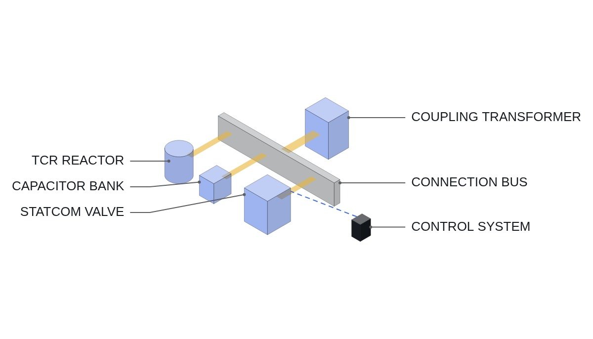
- Access to capacitor banks and valve halls follows “open connection breaker → wait the discharge time set by the standard and manufacturer → close earthing switch → release door key”, with the order enforced by a mechanical key interlock.
- The SVC’s TSC (thyristor-switched capacitor) is fired only when the voltage across the thyristor is near zero. Switching at an arbitrary instant produces a large inrush.
- The SVC’s TCR (thyristor-controlled reactor) generates harmonics, so operation is not permitted unless the harmonic filter branches are energized.
- For a STATCOM, completed DC link precharge and normal valve cooling flow are operating permissives. After shutdown, access is prohibited until DC link discharge is confirmed.
- Confirm in the settings stage the operating order of system protection and compensator protection (overvoltage, overcurrent, unbalance).
How much output is left when voltage drops
One expression captures the difference. With an SVC fully capacitive, output is Q = B_C × V²; with a STATCOM at its current limit, output is Q = V × I_MAX. In per-unit terms, SVC output is proportional to V² and STATCOM output to V.
| Voltage (pu) | SVC output | STATCOM output |
|---|---|---|
| 1.0 | 100 % | 100 % |
| 0.9 | 81 % | 90 % |
| 0.7 | 49 % | 70 % |
| 0.5 | 25 % | 50 % |
Assumptions: the SVC has its TCR off and all capacitors in; the STATCOM is limited at rated current with no short-term overload capability. The table says something simple: at the moment voltage support is needed most — when voltage is lowest — SVC output falls fastest. So a specification must not say only “rated 100 Mvar”; it has to state output at the required voltage, such as “at least y Mvar at 0.x pu”, before the two devices can be compared on the same basis. STATCOM short-term overload capability varies by product and is an item to verify.
Response structure and harmonics
An SVC decides its thyristor firing angle once per half cycle, so its response is quantized in cycle steps. A STATCOM controls current on the PWM switching period, so it responds in finer steps. Near loads that require tracking voltage flicker or fast transients, this difference matters.
On harmonics, the TCR produces low-order harmonics, so filter branches are practically mandatory. For a STATCOM it depends on the topology; a modular multilevel converter (MMC) produces an output waveform with many steps and a small filtering burden. Whether resonance occurs with the system impedance at the installation point, however, is not settled by device type; it requires waveform analysis and field measurement.
Operating permissive and voltage control mode (ST pseudocode)
(* I/O MAP - STATCOM operating permissive supervision *)
(* %I2.0  DI_EMO_CHAIN_OK     : EMO hardwired chain healthy - status monitoring only *)
(* %I2.1  DI_ES_OPEN          : earthing switch open 89E 52b *)
(* %I2.2  DI_DOOR_KEY_LOCKED  : valve hall door key interlock locked *)
(* %I2.3  DI_COOL_FLOW_OK     : valve cooling water flow normal *)
(* %I2.4  DI_DC_PRECHARGE_OK  : DC link precharge complete *)
(* %I2.5  DI_CB_MAIN_CLOSED   : connection breaker 52a *)
(* %IW200 AI_BUS_V_PU         : connection bus voltage pu x 1000 *)
(* %Q2.0  DO_DEBLOCK_PERMIT   : inverter gate deblock permit *)
(* %QW200 AO_Q_REF_PU         : reactive power command pu x 1000 *)
(* SCADA link : V_REF and SLOPE received via IEC61850_MMS *)

B_START_PERMIT := DI_EMO_CHAIN_OK AND DI_ES_OPEN AND DI_DOOR_KEY_LOCKED
                  AND DI_COOL_FLOW_OK AND DI_DC_PRECHARGE_OK
                  AND DI_CB_MAIN_CLOSED;

(* low cooling flow stops after a manufacturer-defined delay, not instantly - example 2 s *)
TON_COOL(IN := NOT DI_COOL_FLOW_OK, PT := T#2S);
IF TON_COOL.Q THEN B_START_PERMIT := FALSE; END_IF;

DO_DEBLOCK_PERMIT := B_START_PERMIT;

(* voltage control with slope (droop) *)
R_V_MEAS := INT_TO_REAL(AI_BUS_V_PU) / 1000.0;
R_Q_REF  := (R_V_REF - R_V_MEAS) / R_SLOPE;     (* R_SLOPE example 0.03 pu/pu *)

(* current limit - since Q = V x I_MAX, the limit also falls at low voltage *)
R_Q_LIM := R_V_MEAS * R_I_MAX_PU;
IF R_Q_REF >  R_Q_LIM THEN R_Q_REF :=  R_Q_LIM; END_IF;
IF R_Q_REF < -R_Q_LIM THEN R_Q_REF := -R_Q_LIM; END_IF;

IF DO_DEBLOCK_PERMIT THEN
    AO_Q_REF_PU := REAL_TO_INT(R_Q_REF * 1000.0);
ELSE
    AO_Q_REF_PU := 0;
END_IF;
The actual current control loop runs inside the device controller at sub-millisecond rates; the code above shows only the permissive and command limiting in the supervisory layer. R_SLOPE and the 2 s delay are examples. A zero slope can make the compensator fight neighbouring compensators or generator AVRs, so the setting must be coordinated with the other voltage control devices at the installation point.
SVC versus STATCOM
| Item | SVC | STATCOM |
|---|---|---|
| Principle | Variable admittance (TCR+TSC) | Voltage-source inverter as current source |
| Low-voltage output | Proportional to V² | Proportional to V (current limit) |
| Response step | Half cycle | Switching period |
| Harmonic measures | Filter branches required | Topology-dependent, small for MMC |
| Footprint | Large reactor and capacitor banks | Relatively small |
| Main maintenance | Capacitor units, reactors | Semiconductor valves, cooling |
Only the second row changes the conclusion. The other rows can be adjusted with site conditions and budget, but low-voltage output comes from the operating principle and cannot be changed by settings. Conversely, in an application where voltage stays near nominal, the second-row difference disappears and the decision moves to footprint and cost.
Boundary conditions — where the STATCOM advantage disappears
If the purpose is steady-state power factor correction or gradual voltage adjustment with load changes, at a strong point in the network where fault voltage dips are shallow, the STATCOM’s low-voltage characteristic is rarely used. There, an SVC, or mechanically switched capacitors (MSC) combined with a small STATCOM, can secure Mvar more economically for the equipment involved.
Conversely, at weak points such as renewable connection points where post-fault voltage recovery is part of the connection conditions, or where voltage stability limits are an operating constraint, the STATCOM advantage grows. Which case applies should first be confirmed by system studies of the fault voltage trajectory at the installation point.
The single decision rule: write the requirement as “Mvar at the lowest fault voltage”; if that makes the SVC disproportionately larger than the STATCOM, choose the STATCOM, and if only near-nominal operation is required, choose the SVC.