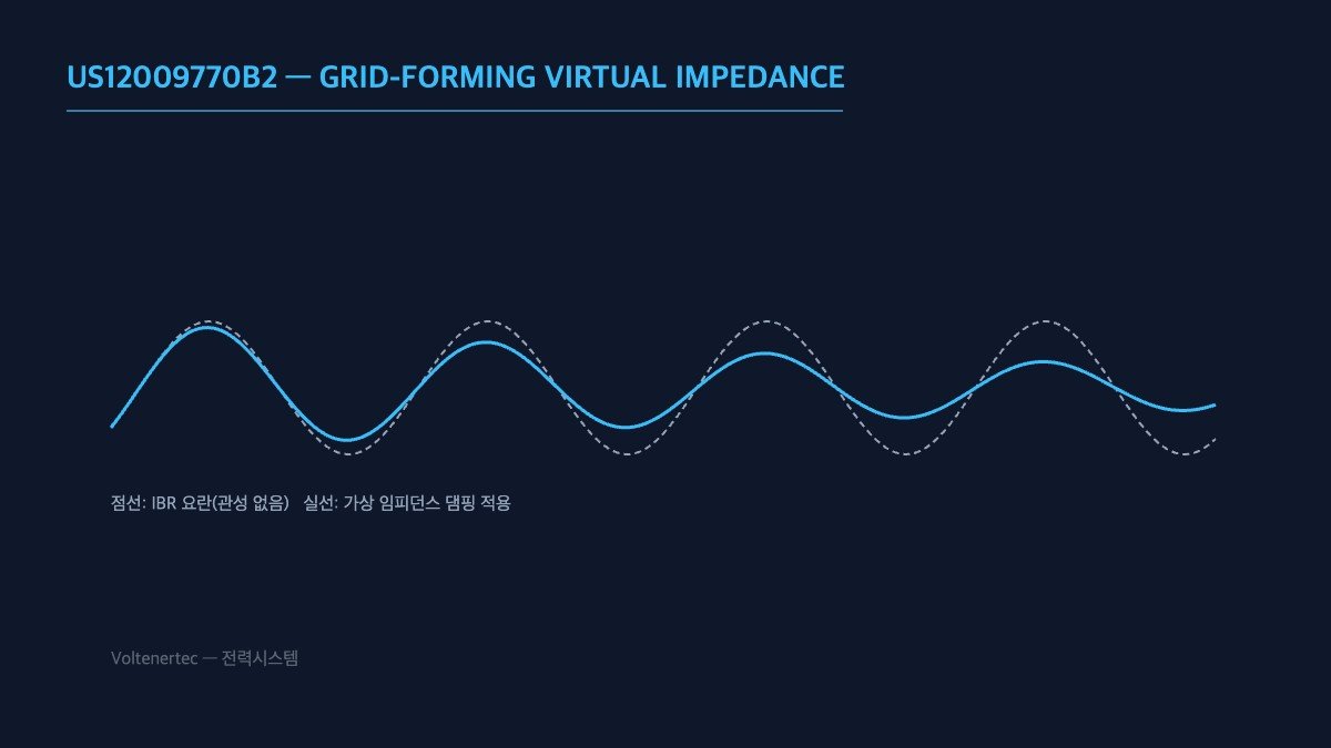
As the share of inverter-based resources (IBR) grows, grid inertia decreases and frequency response becomes unstable. GE Vernova’s granted patent US12009770B2 (“System and method for providing grid-forming control of an inverter-based resource”) approaches this problem through virtual impedance tuning. Under what conditions does this approach work, and under what conditions do its limits show?
Grid-forming control is a method in which the inverter creates its own voltage and frequency reference, much like a synchronous generator. Tuning virtual impedance means emulating the inertia and damping characteristics of a real generator in software to improve grid stability and frequency response. Now that solar has passed 3 TW and the IBR share keeps rising, the practicality of this kind of software-based inertia is being put to the test.
| Item | Details |
|---|---|
| Patent number | US12009770B2 |
| Applicant | GE Vernova |
| Core technology | Virtual impedance tuning in grid-forming (GFM) control |
| Purpose | Improved grid stability and frequency response |
What this table says — virtual impedance tuning is cost-effective in that it secures inertia using only the control logic of existing inverters, without adding hardware. However, a safety circuit (EMO) cannot be replaced by this kind of software workaround. Grid-forming is a stability improvement for normal operation; it does not take over the safety functions of fault-current response and protection coordination, and that is its limit.
Checkpoint you can apply right away — If you are considering grid-forming inverters, the first step is to ask the supplier for test data showing that the virtual impedance parameters stay stably tuned as grid impedance changes (seasonal load variation and the like).
What virtual impedance changes at the equipment level
From the equipment side, the key word in the patent title is “grid-forming.” A grid-following inverter measures the grid voltage and injects current in step with it; it needs a stable grid to follow. A grid-forming inverter does the opposite: it behaves as a voltage source behind an impedance and lets the current settle wherever the grid pulls it. That is what makes it look like a synchronous generator to the rest of the network.
In a real generator, the impedance between the internal voltage and the terminals is a physical property of the machine. In an inverter, that impedance is whatever the control loop says it is. Virtual impedance is therefore a design choice made in firmware, and tuning it sets how strongly the inverter resists changes in voltage and frequency and how quickly those disturbances are damped. This is the source of both the cost advantage and the risk: nothing new has to be installed, but a poorly tuned value is just as easy to deploy as a good one.
The other point an equipment engineer should keep in mind is that the emulation stops at the control loop. A synchronous machine can deliver high fault current because of its physical construction. An inverter’s current is limited by its semiconductor ratings no matter what impedance the software emulates. That is why the post separates stability improvement during normal operation from fault-current response and protection coordination: the first is a control function, the second depends on hardware.
Where it wins, where it doesn’t
Current condition: on a network with a high IBR share, fewer synchronous machines remain to provide inertia, and frequency response weakens. After applying virtual impedance tuning: existing inverters begin to contribute inertia and damping through control logic, improving stability without additional hardware. Linking logic: the approach wins where the problem is a lack of inertia during normal operation and where parameters can be validated against the grid conditions the inverter will actually see. It does not win where the problem is fault current or protection, because those are not solved by control tuning.
Character comparison: grid-following and grid-forming
| Aspect | Grid-following | Grid-forming |
|---|---|---|
| Voltage reference | Taken from the grid | Created by the inverter |
| Behavior to the grid | Current source | Voltage source behind impedance |
| Inertia contribution | None by itself | Emulated in control |
| Main tuning risk | Loss of synchronism on weak grids | Parameters unsuited to grid impedance |
| Fault current | Limited by hardware rating | Limited by hardware rating |
The row to read carefully is the last one: it is the same in both columns. Grid-forming changes how the inverter behaves during normal operation and disturbances, but it does not change the hardware limit on fault current. Protection coordination therefore has to be verified on its own terms, not assumed to improve because the control mode changed.
Items to check before adoption
- Confirm that the EMO and hardwired protective trips open the inverter output independently of the grid-forming control; no control mode or parameter set may bypass or delay them.
- Request supplier test data for the virtual impedance parameters across the range of grid impedance expected at the point of connection, including seasonal load variation.
- Review protection coordination with the inverter’s actual fault-current capability, separately from its grid-forming behavior.
- Define who owns parameter changes after commissioning and how changes are validated, since the impedance lives in firmware and can be altered without any visible hardware change.
- Treat oscillation or interaction with neighboring inverters as an open question until confirmed on site; it requires waveform analysis and field measurement.
Boundary conditions
The advantage of software-based inertia depends on the grid impedance staying within the range the parameters were tuned for. If the network topology changes, if nearby resources are added or removed, or if seasonal load shifts move the impedance outside the validated range, the same parameters that improved stability can degrade it. And under fault conditions, the benefit of virtual impedance gives way to the hardware limits of the inverter and the protection scheme. The single decision criterion is this: adopt virtual impedance tuning only where the supplier can show stable behavior across the grid impedance range actually present at the connection point.
Source: Google Patents