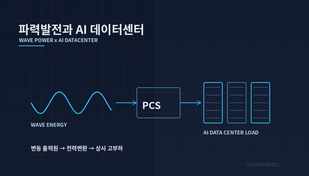
Bottom line first. The core of the AI data center grid code the Korean government says it will issue this year is to set the conditions under which the grid will accept “a load that swings by megawatts within milliseconds.” On the equipment side, that is a question of power (MW) and response speed, not energy (MWh). If swings only need to be absorbed for a few seconds, the energy required is small but the power required is large. Data center-side mitigation is therefore likely to favor a dedicated power-type buffer designed to survive repeated micro-cycling, rather than reusing the backup UPS batteries as they are. The detailed criteria of the grid code have not been published, so numeric thresholds need revisiting once they are final.
What was reported
On September 21, Energy News (에너지신문) summarized the government’s AI data center plan and the grid-access problem. The government plans a total of 18.4 GW of AI data centers by 2035, reaching the target by building 8.4 GW in phase one and then through further expansion by SK. The article identified the key challenge: even with large investments and servers secured, compute infrastructure cannot be guaranteed to run if power is not available when needed.
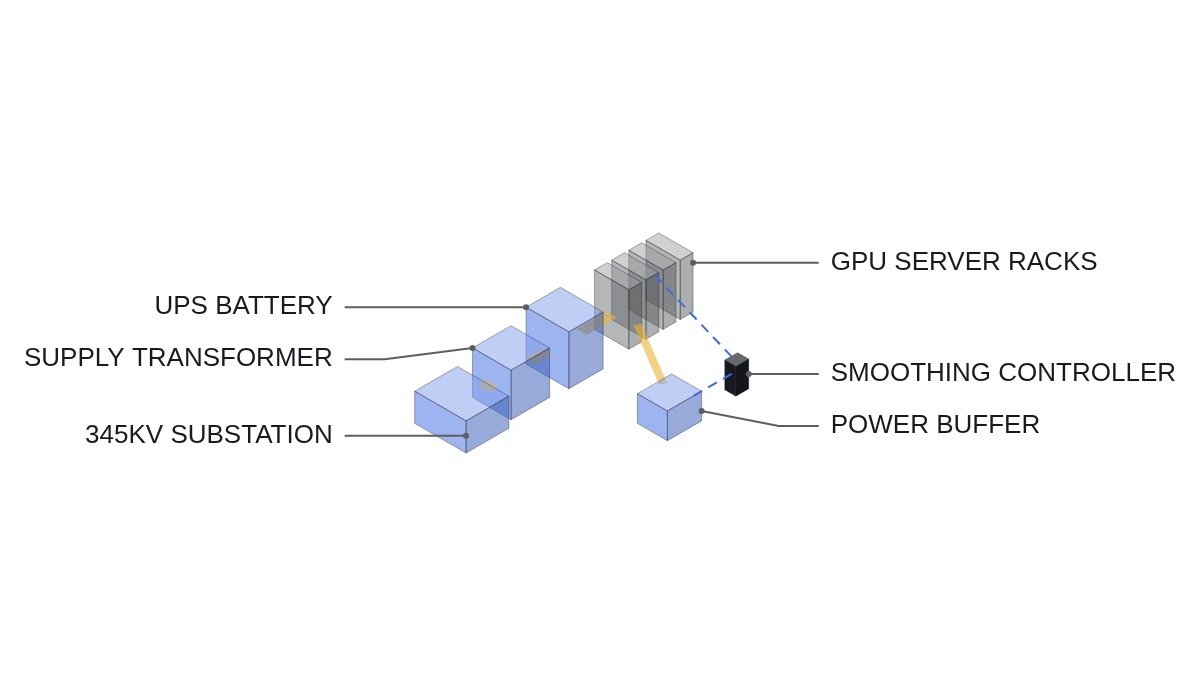
The government response has three strands: publishing information on 345 kV substations with spare capacity to steer demand toward areas with grid headroom; having KEPCO expand transmission and substations pre-emptively; and setting connection and operating rules suited to AI loads. The Ministry of Climate, Energy and Environment plans to prepare an AI data center grid code within the year, citing the possibility of MW-scale power swings on a millisecond scale during AI training and inference.
Remaining tasks listed were demand verification separating long-term targets from firmly committed investment, cost-sharing between individual data centers and shared grid assets, and schedule alignment with the 12th Basic Plan for Electricity Supply and Demand and the transmission plan. The article concluded that the competitive yardstick will be not the announced GW figure but “from when can stable power actually be used.”
Phase one’s 8.4 GW is about 46% of the 18.4 GW target. The remaining 10 GW depends on further expansion, so grid planning will inevitably reflect committed and target volumes in separate stages. Since the grid code will apply to both stages, it is an item that needs to be settled before individual projects.
Where it wins, where it doesn’t
Current conditions
Until now a data center has looked to the grid like “a large but flat load.” Supply design focused on maximum demand and redundancy; the rate of load change was secondary. UPS batteries are designed as backup to ride through until generators start, and their life is rated on the assumption that they barely cycle in normal operation.
What changes with a grid code
In AI training, many accelerators move between compute and communication in the same step at the same time, so power can rise and fall in steps. If the grid code caps this rate of change or requires smoothing, the data center becomes both a load and “an asset whose output swings must be managed.” The ramp-rate management concept applied to renewable generators moves over to the load side.
The connecting logic
Ramp-rate management depends on instantaneous power and response speed more than on stored energy. The energy needed to cover swings lasting a few seconds is small, but repeating it thousands of times a day wears out cell cycle life first. The selection criterion therefore shifts from “how many minutes can it hold” to “how many times a day, how many MW, delivered and absorbed within how many ms.”
Power and energy needed to absorb the swings
For illustration, a calculation with assumed values. Assumptions: a data center with 100 MW supply capacity, a 30 MW load swing within 100 ms, smoothed over 10 seconds to reduce the rate of change the grid sees. These numbers are not from the article; they are a worked example.
- Rate of change: 30 MW ÷ 0.1 s = 300 MW/s
- Energy required for smoothing (upper approximation): 30 MW × 10 s = 300 MJ = 300 ÷ 3.6 ≈ 83.3 kWh
- C-rate needed to deliver that energy at 30 MW: 30,000 kW ÷ 83.3 kWh ≈ 360C (territory for power devices, not cells)
What this shows is that the energy is small, under 100 kWh, while the power equals 30% of supply capacity. In practice the design would use a larger battery at a lower C-rate, but the conclusion that the decision variables are MW and cycle count, not kWh, holds even when the assumptions change.
| Measure | Location | Response | Limitation |
|---|---|---|---|
| Grid reinforcement | Substation, transmission | Continuous | Long build time, cost-sharing disputes |
| Reactive compensation (STATCOM etc.) | Point of supply | Fast | Cannot cover active power swings |
| Reuse existing UPS batteries | Inside data center | Fast | Eats backup capacity, consumes cycle life |
| Dedicated power-type buffer | Inside data center | Very fast | Extra equipment cost, space |
| Load-side software smoothing | Servers, job scheduler | Depends on settings | Possible compute efficiency loss |
The third row is the most commonly chosen option and the most dangerous one. If UPS batteries are shared for ramp smoothing, an outage can arrive when part of the backup energy has already been spent on smoothing. If they are shared, a separate backup-only SOC floor must be set and the smoothing function must operate only above that floor, with the operating conditions kept separate.
Checks at the supply design stage
- Safety first: confirm that the emergency-off paths of the incoming breaker and UPS output breakers are hardwired and that the smoothing control logic does not intervene in them.
- Capture the load profile: record actual power waveforms at ms resolution according to the training/inference mix. Swing size and period vary by facility and require waveform analysis and field measurement.
- Swing size versus short-circuit capacity at the connection point: the same 30 MW swing has less voltage impact on a strong grid. The published 345 kV headroom information feeds this judgment.
- Buffer specification: fix required power (MW), response time (ms) and daily cycle count first; set energy (kWh) last.
- Backup separation: if the UPS is shared, define the backup-only SOC floor and the permitted smoothing band separately.
- Items to verify: the grid code’s ramp-rate cap, measurement window length and the size threshold for application have not been published.
Boundary conditions
The case for a power-type buffer reverses under the following conditions. First, when operation is inference-dominated and many independent jobs overlap statistically so that the load flattens itself; the buffer then delivers little for its cost. Second, when the data center is small enough relative to the short-circuit capacity at the connection point that the grid absorbs the swings as they are. Third, when the grid code is written as a grid-reinforcement cost contribution rather than a ramp-rate cap; the incentive to install a buffer then becomes a cost comparison.
The single decision rule is this: install a power-type buffer separate from the backup UPS only when the measured load swing (MW) exceeds the fluctuation allowed at the connection point and that swing repeats several hundred times a day or more.
References
- Energy News (에너지신문), “AI 데이터센터 18.4GW 청사진…성패 가를 ‘전력망 접속'” (An 18.4 GW AI data center blueprint: grid access will decide success), 2026-09-21, https://www.energy-news.co.kr/news/articleView.html?idxno=228455