VOLTENERTEC WEEKLY · 2026 Week 38 · 1/5
To state the conclusion first: results showing that the stack pressure of sulfide-based solid-state batteries can be lowered to roughly 0.2 MPa have been reported, but at this point that is not yet grounds for removing the pressing jig from assembly equipment. What needs to change is not whether a jig exists, but the pressure measurement point and interlock (인터락) conditions. Equipment whose purpose was a restraint frame capable of withstanding tens of MPa now becomes equipment that must precisely maintain and monitor pressure in the 0.2 MPa band — a regime where measurement resolution becomes quality itself.
What Was Reported — Data by Stack-Pressure Condition
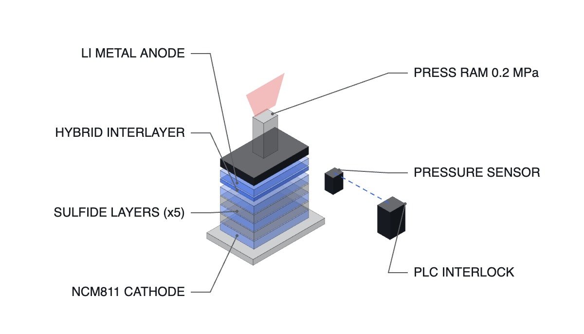
A research team led by Professor Park Su-jin and Dr. Song Young-jin of the POSTECH Department of Chemistry, together with Professor Cho Chang-sin’s team from the Department of Battery Engineering and Department of Chemical Engineering, reported that inserting a 2–4 μm (0.002–0.004 mm) thin-film hybrid interfacial layer combining MXene, silicon (Si), and silver (Ag) between the lithium anode and the solid electrolyte reduced the stack-pressure dependence of sulfide-based solid-state batteries. The results were published in the international journal Advanced Energy Materials.
| Configuration | Required Stack Pressure | Cycling Result | Precondition |
|---|---|---|---|
| Conventional sulfide-based solid-state | Tens of MPa | No figure given in press release | Requires large, heavy restraint fixture |
| Solid-state with silicon added | 5 MPa | No figure given in press release | Based on prior reported cases |
| Cell with MXene-Si-Ag interfacial layer | ~0.2 MPa | 72.4% of initial capacity after 200 cycles | NCM8 cathode, 4.18 mAh/cm² |
| Pouch cell, same interfacial layer | Ultra-low-pressure condition | 82.7% after 200 cycles | 3×3 cm² (30×30 mm) cell |
The table says one thing. When stack pressure drops from tens of MPa to 0.2 MPa — more than an order of magnitude — pressure changes character from a structural design variable to a process measurement variable. A frame holding tens of MPa could tolerate large tolerances as long as it did not exceed the target pressure; in the 0.2 MPa band, the same absolute error becomes an error of tens of percent. The criterion for selecting instrumentation shifts from pressure rating to resolution and linearity.
The Advantaged Position and the Disadvantaged Position
Under current conditions, the pressing equipment on a solid-state pilot line generates tens of MPa of areal pressure using hydraulic or high-capacity servo presses, and the restraint frame and reaction structure needed to hold that pressure occupy a substantial share of the volume around the cell. Pressure measurement usually relies on indirect estimation from ram torque or hydraulic line pressure.
Once stack pressure drops into the 0.2 MPa band, this structure is inverted. The reaction structure shrinks, but indirect estimation can no longer hit the target value, because conversion error in hydraulic line pressure carries straight through as areal-pressure error. The configuration must move to placing a load cell or thin-film pressure sensor directly beneath the cell-stack face to measure areal pressure directly, and this measured value becomes both the termination condition of the pressing sequence and the input to the interlock.
The chain of reasoning follows from there. When measurement shifts from indirect to direct, the failure mode shifts too. Previously, overpressure was the primary risk; in an ultra-low-pressure process, pressureless pressing caused by sensor open-circuit or drift (the process judged complete while no pressure has actually been applied) is more dangerous. A cell whose interfacial gap never closed then flows through as a passed unit.
Safety Interlock Verification Order
When laying out a new pressing-station sequence, the verification order below applies. Do not change the order.
- Confirm that the EMO (Emergency Off) hardwired circuit directly cuts power to the pressing-ram drive. The EMO does not pass through PLC logic and is never bypassed or substituted by software. The PLC only reads the EMO contact state.
- Confirm that the safety door and light-curtain contacts (DI) are wired in series with the ram-descent permit condition.
- Monitor the deviation between the two pressure-sensor channels (main and monitor). Pressing is prohibited if the deviation between the two measured values exceeds the allowable limit. Do not operate the ultra-low-pressure process on a single sensor channel alone.
- Set the pressureless-detection condition. If the ram-descent-complete signal is received but areal pressure has not crossed the lower limit, do not judge the process complete — raise an alarm instead.
- Set the overpressure upper limit. Even with a 0.2 MPa target, momentary overshoot can occur from the inertia of the ram drive train, so the ram must stop immediately if the upper limit is exceeded.
- Monitor pressure drift during the pressure-hold period. Log the interval in which areal pressure falls due to changes in cell thickness.
Pressing-Station Sequence (ST Pseudocode)
(* I/O MAP *)
(* DI101 : EMO CONTACT OK - hardwired EMO circuit state, read-only *)
(* DI102 : SAFETY DOOR CLOSED *)
(* AI101 : MAIN LOAD CELL 0.00 - 1.00 MPa *)
(* AI102 : MONITOR LOAD CELL 0.00 - 1.00 MPa *)
(* DO101 : PRESS RAM DOWN ENABLE *)
(* DO102 : PROCESS COMPLETE LAMP *)
(* DO103 : ALARM *)

AI_STACK_PRESSURE := AI101;
AI_STACK_PRESSURE_M := AI102;
DI_EMO_OK := DI101;
DI_DOOR_CLOSED := DI102;

(* 1. Two-channel sensor deviation check - prohibit pressing if deviation exceeds 0.02 MPa *)
IF ABS(AI_STACK_PRESSURE - AI_STACK_PRESSURE_M) > 0.02 THEN
B_SENSOR_FAULT := TRUE;
END_IF;

(* 2. Pressing permit - only when EMO / door / sensor are all normal *)
DO_PRESS_RAM_ENABLE := DI_EMO_OK AND DI_DOOR_CLOSED AND NOT B_SENSOR_FAULT
AND (AI_STACK_PRESSURE < R_PRESS_MAX); (* R_PRESS_MAX = 0.25 MPa *)

(* 3. Overpressure - stop ram immediately and alarm if upper limit exceeded *)
IF AI_STACK_PRESSURE >= R_PRESS_MAX THEN
DO_PRESS_RAM_ENABLE := FALSE;
DO_ALARM := TRUE;
END_IF;

(* 4. Pressureless-pressing detection - if ram descent is complete but pressure is below the lower limit, do not judge complete *)
IF B_RAM_DOWN_DONE AND (AI_STACK_PRESSURE < R_PRESS_MIN) THEN (* R_PRESS_MIN = 0.15 MPa *)
DO_PROCESS_COMPLETE := FALSE;
DO_ALARM := TRUE;
END_IF;
The R_PRESS_MAX and R_PRESS_MIN values are illustrative examples set against the reported figure above (0.2 MPa). In an actual production line, these must be determined from cell specifications and measurement uncertainty; they are not values this article can finalize.
The Interfacial-Layer Approach, Seen Through Patents
The approach of lowering interfacial resistance by inserting an intermediate layer between the solid electrolyte and the electrode is itself already secured by a granted patent. US10971761B2, “Interfacial layers for solid-state batteries and methods of making same,” assigned to the University of Maryland, College Park, claims one or more interfacial layers in contact with a solid electrolyte, describing that the interfacial layer — composed of inorganic materials, metal oxides, polymers, gels, or ion-conductive liquids — lowers the impedance of the interface between the cathode or anode and the solid electrolyte. Filed 2015-10-28, granted 2021-04-06; current legal status is Active, with an anticipated expiration of 2035-10-28.
In other words, the direction of this solution — an interfacial layer — is already an area with an established patent landscape. What differentiates this new report is not the presence of an interfacial layer, but that it disperses lithium growth sites by separating the roles of a fixed seed (silicon) and a mobile seed (silver).
Boundary Conditions — When This Advantage Reverses
The advantage of ultra-low pressure disappears under three conditions.
First, cycle life. 72.4% after 200 cycles (82.7% after 200 cycles for the pouch cell) is research-stage data, some distance from the cycle-life range required of mass-produced automotive cells. It is not yet a number that can be reflected in equipment specifications.
Second, area. The verified pouch cell is 3×3 cm² (30×30 mm). As area increases, pressure uniformity becomes an issue, and in the 0.2 MPa band the same absolute deviation shows up as a much larger relative error. At large area, flatness and parallelism control is likely to become the new bottleneck in place of reduced pressing equipment — this is not asserted definitively, since measured data at large area has not been disclosed.
Third, process steps. A 2–4 μm interfacial layer means an added deposition or transfer process. Whether the equipment investment and process time saved on the pressing side offsets the added interfacial-layer process must be calculated at the line level.
The single selection criterion is therefore set as follows: only lines that first establish a measurement system capable of directly measuring and verifying areal pressure in the 0.2 MPa band should consider reducing their pressing structure. If measurement still relies on indirect estimation, there is nothing yet to change in the equipment even as stack pressure comes down.
Source: Electric Times article (in Korean), September 14, 2026