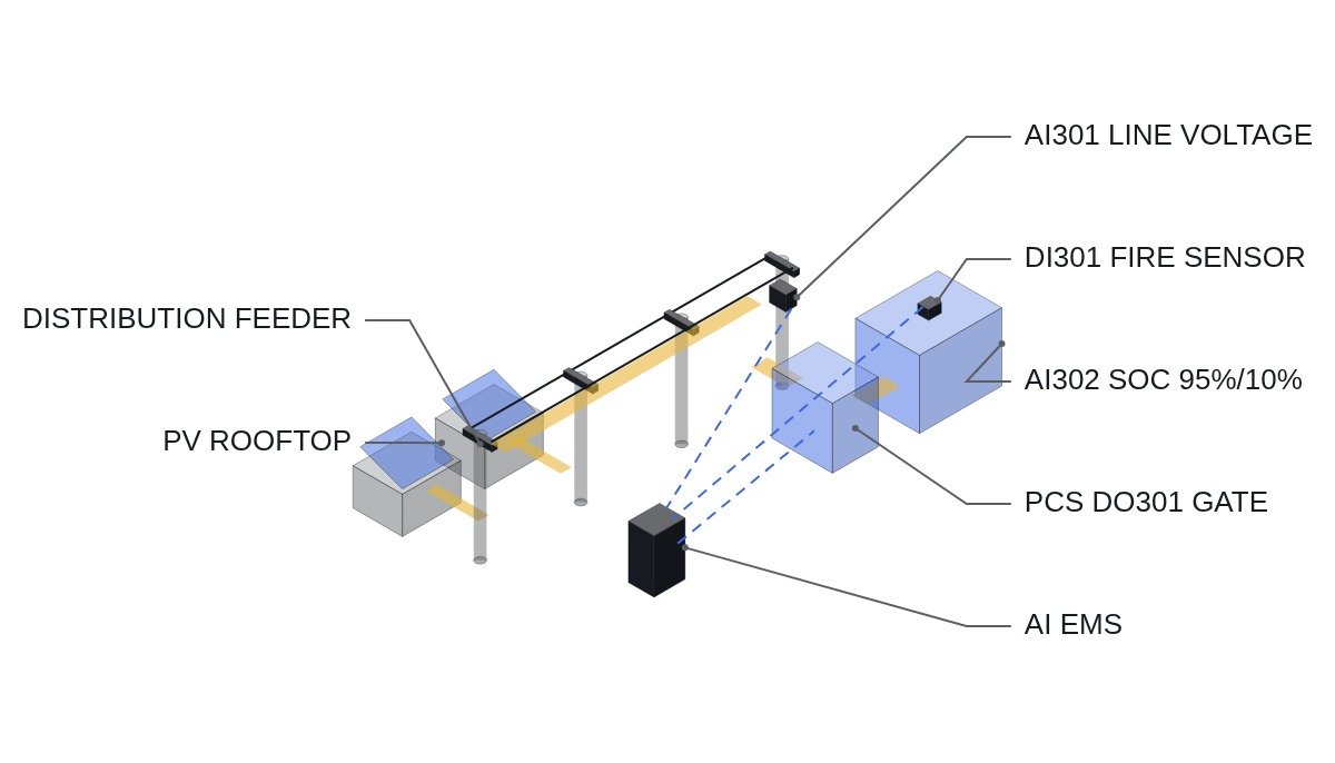
A distribution-grid ESS is a grid asset installed on distribution feeders whose transmission connection capacity is saturated, to absorb and release solar output. The programme began in July 2026 when the Ministry of Climate, Energy and Environment signed agreements with nine VPP (virtual power plant) operators. As it entered its second round of tenders in August, covering about 50 distribution feeders on the mainland and 7 in Jeju, a new condition was added: next-generation batteries with long-duration, long-life and fire-safety characteristics are to be applied preferentially in Jeju. The conclusion first: interlock priorities for a distribution-grid ESS must be designed differently from those of a general ESS PCS — the distribution feeder voltage and capacity interlock must always sit above the battery’s own protection interlocks.
In a distribution-grid ESS, monitoring of feeder voltage and capacity limits must sit above battery self-protection in the safety interlock hierarchy, because the purpose of this equipment is to secure distribution grid connection headroom, not to protect the battery asset.
Preconditions: Because exact drive sequence information for individual sites has not been provided, the checklist below is developed from the general specifications published for the Ministry’s distribution-grid ESS programme (July 2026 agreements, August second-round tender) — AI-based charge/discharge control, solar add-on connection type. In actual application, it must be replaced and confirmed with procedures based on each operator’s EMS (energy management system) specification.
Safety interlock check order (top priority)
- Distribution feeder voltage and capacity interlock — block the charge gate when feeder voltage exceeds the upper limit, and block the discharge gate when it goes past the lower limit (feeder protection first)
- SOC (state of charge) upper/lower limit interlock — block charging when SOC reaches the upper limit (95%) and block discharging when it reaches the lower limit (10%) (prevents battery degradation)
- Fire detection-suppression interlock — when fire detection is confirmed, start the automatic suppression system and block all PCS gates at the same time
- AI charge/discharge prediction logic fault interlock — switch to manual mode when the deviation between predicted and measured values exceeds a threshold; the AI logic is not used to bypass grid protection circuits
- EMO (emergency stop) — the principle is a configuration in which hardware wiring directly blocks the PCS gates; designs that replace or bypass the EMO function with software logic alone are not covered on this site.
Distribution-grid ESS interlock checklist (I/O map)
| Signal | I/O address | Type | Operating condition |
|---|---|---|---|
| Feeder voltage | AI301 | Analog In 4-20mA | Charge blocked above upper limit, discharge blocked past lower limit |
| SOC | AI302 | Analog In 4-20mA | Charge blocked at 95% or above, discharge blocked at 10% or below |
| Fire detection | DI301 | Digital In | 1 = detected → start suppression + block gates |
| EMO pressed status | DI302 | Digital In (hardwired) | 1 = pressed → no PLC bypass, gates blocked directly |
| AI prediction-measurement deviation alarm | DI303 | Digital In | 1 = threshold exceeded → switch to manual mode |
| PCS gate enable | DO301 | Digital Out | Outputs 1 only when all interlocks are normal |
The implication of this checklist is clear: AI301 (feeder voltage) must be placed as a higher-level interlock than AI302 (SOC). Grid protection takes precedence over battery protection because the purpose of this equipment is to secure distribution grid connection headroom, not to protect the battery asset.
PLC logic snippet (IEC 61131-3 Structured Text pseudocode)
(* Distribution-grid ESS PCS gate enable logic *)
(* AI301: feeder voltage (%), AI302: SOC (%), DI301: fire detection, DI303: AI deviation alarm *)
IF DI301 = 1 THEN
    DO_PCS_GATE_ENABLE := FALSE; (* fire detection confirmed, highest-priority block *)
ELSIF AI301 > 106.0 OR AI301 < 94.0 THEN
    DO_PCS_GATE_ENABLE := FALSE; (* feeder voltage outside upper/lower limits *)
ELSIF DI303 = 1 THEN
    DO_MANUAL_MODE_REQUEST := TRUE; (* AI prediction deviation exceeded, request manual mode *)
ELSIF AI302 >= 95.0 THEN
    DO_CHARGE_GATE_ENABLE := FALSE; (* SOC upper limit, block charging *)
ELSIF AI302 <= 10.0 THEN
    DO_DISCHARGE_GATE_ENABLE := FALSE; (* SOC lower limit, block discharging *)
ELSE
    DO_PCS_GATE_ENABLE := TRUE;
END_IF;
Boundary conditions: responding to field variables
As of August 2026, the second-round tender is still in progress, and the detailed evaluation criteria for next-generation batteries (long-duration, long-life, fire-safety) and the size of the Jeju preference have not yet been finalised and announced. If the AI-based charge/discharge prediction algorithm cannot track rapid weather-driven changes in solar output (such as passing clouds) in real time, SOC management may fail and the effect on relieving output curtailment may fall short of expectations — requires waveform analysis and field measurement. The selection criterion comes down to one question: has the EMS placed the feeder voltage interlock (AI301) above the SOC interlock (AI302)?
References
Newspim, “Korea East-West Power builds Korea‘s first ‘renewable add-on connection ESS’… 60 MWh” (2026.07.14)
Asia Today, “Ministry of Climate to resolve solar connection bottlenecks in Honam and Jeju… 700 MW of ESS” (2026.07.10)
KR101836439B1, Telda Co., Ltd., “System for predicting charge/discharge algorithm of ESS installed at power consumer” (Google Patents)