To state the conclusion first: the electrical design basis for agrivoltaics differs from a conventional ground-mount plant in one premise. It is a power plant where people and farm machinery are underneath the array all the time. That premise shifts the interlock basis from “access during maintenance” to “continuous occupancy,” and farm schedules such as irrigation and spraying shake insulation monitoring values and string current distribution on a seasonal scale. Module layout and inverter configuration are set within the constraints of crop yield, so the electrical side should respond not by changing the layout but by fitting string grouping and MPPT allocation to it.
Safety interlocks: write them for continuous occupancy
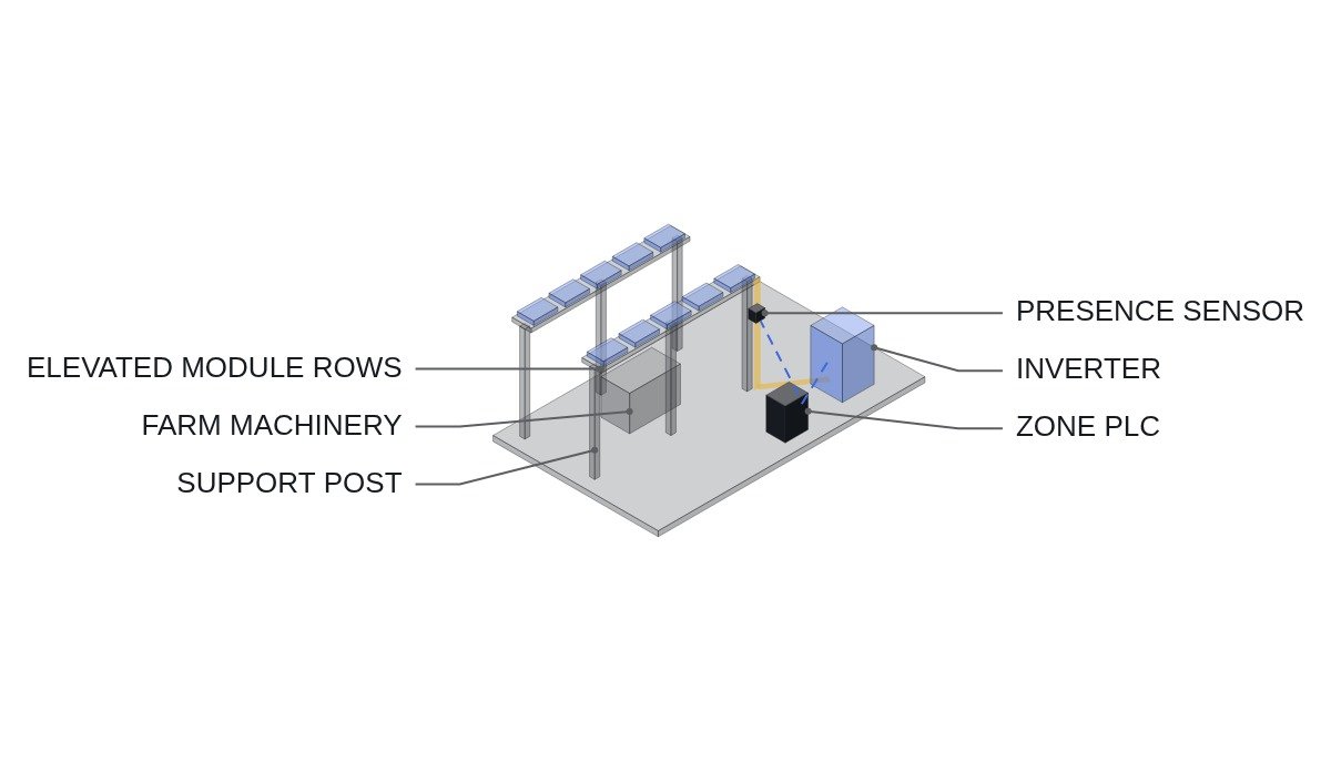
At a conventional ground-mount plant, only authorized people enter the fence; at an agrivoltaic site, the farmer works under the array from sowing to harvest. Check shock protection and drive interlocks against this condition first.
- □ Confirm that the emergency off (EMO) opens each zone’s AC breaker, the inverter external-stop terminals, and the tilt drive power through hardwiring. Place EMO buttons where they can be reached from several points in the field. The PLC only monitors the EMO loop.
- □ Fix DC cables above the working height of farm machinery or run them in conduit, and add impact guards at exposed sections near the bottom of the posts.
- □ If the structure adjusts module tilt to crop conditions, include people and machinery detection in the zone in the drive run permit. Design it so that a detection sensor fault inhibits the drive.
- □ Never disable the inverter’s own residual current and insulation protection in any farm-work mode. The PLC uses farm-work signals only to classify alarm causes.
- □ Include “modules and cables are always live in daylight” in the farmers’ safety training, and post signs at zone entrances.
Operating conditions compared with ground-mount
| Item | Ground-mount | Agrivoltaic |
|---|---|---|
| Occupancy under array | Maintenance staff, intermittent | Farmers and machinery, continuous |
| Module layout | Dense, set by yield | Wider spacing, set by crop sunlight |
| Rear-side reflection | Ground, little seasonal change | Changes with crop growth |
| Wetting | Mainly rain | Irrigation and spraying added |
| Cable routing | Short, can be buried | Longer from spacing, burial limited |
| Output adjustment | Grid commands | Grid commands + crop conditions (adjustable type) |
Of the six rows, the only ones an electrical designer controls are cable routing and string configuration. The rest are set by the crop and the farm work, so interlock and monitoring logic must take these variables as inputs and correct its judgments accordingly. In particular, when rear-side reflection changes with the season, current deviation between bifacial module strings changes with it.
String and MPPT configuration checklist
- □ Overlay crop row direction on the module row layout in the drawings, and group modules under the same row conditions into the same string.
- □ Assign edge rows (zone perimeter) and interior rows to different MPPT inputs, since their rear-side reflection differs.
- □ For strings with longer cable runs, calculate voltage drop and confirm the margin to the lower limit of the MPPT input voltage range. Assumption: string current 10 A, 400 m round trip, 4 mm2 copper (about 4.6 Ω/km at 20°C) gives a drop of 10 A × 0.4 km × 4.6 Ω/km ≈ 18.4 V.
- □ Check irrigation piping and sprinkler coverage, and place junction boxes and connectors out of the direct spray path.
- □ For adjustable structures, record tilt history and generation on the same time axis so that output reduction from crop-priority operation can be told apart from equipment faults.
PLC logic example
(* IEC 61131-3 ST pseudocode - agrivoltaic zone B: drive permit + farm-work alarm classification *)
(* %I0.0   DI_EMO_LOOP_HEALTHY     : EMO hardwired loop healthy (1) - monitoring only *)
(* %I4.0   DI_ZONE_B_PRESENCE      : zone B people/machinery detected (1 = detected) *)
(* %I4.1   DI_ZONE_B_SENSOR_OK     : detection sensor self-diagnosis OK (1) *)
(* %I4.2   DI_IRRIGATION_B_RUN     : zone B irrigation pump running (1) *)
(* %I4.3   DI_INV_B_ISO_WARN       : inverter B insulation degradation warning (1) *)
(* %IW400  AI_WIND_MS              : wind speed (m/s, scale 0.1) *)
(* %Q4.0   DO_TILT_B_RUN_PERMIT    : zone B tilt drive permit *)
(* %Q4.1   DO_ISO_ALARM_B_TRUE     : insulation alarm (not farm-related, inspect now) *)
(* %Q4.2   DO_ISO_NOTE_B_IRRIG     : insulation drop record (coincides with irrigation, trend watch) *)

VAR CONSTANT WIND_MAX : INT := 150; END_VAR   (* example: 15.0 m/s - confirm against structural design conditions *)

(* 1. drive: permit only with nobody present + sensor OK + wind below limit - inhibit on sensor fault *)
DO_TILT_B_RUN_PERMIT := DI_EMO_LOOP_HEALTHY AND DI_ZONE_B_SENSOR_OK
                        AND NOT DI_ZONE_B_PRESENCE AND (AI_WIND_MS < WIND_MAX)
                        AND TILT_B_REQUEST;

(* 2. insulation warning classification: inverter protection acts as-is, PLC only classifies *)
TOF_IRRIG(IN := DI_IRRIGATION_B_RUN, PT := T#2H);   (* irrigation influence window until 2 h after it stops *)
IF DI_INV_B_ISO_WARN THEN
    IF TOF_IRRIG.Q THEN
        DO_ISO_NOTE_B_IRRIG := TRUE;                 (* irrigation-linked - record in trend data *)
        DO_ISO_ALARM_B_TRUE := FALSE;
    ELSE
        DO_ISO_ALARM_B_TRUE := TRUE;                 (* drop unrelated to irrigation - inspect now *)
    END_IF;
END_IF;

(* 3. escalate to immediate inspection if irrigation-linked records reach 3 within 7 days *)
IF IRRIG_NOTE_COUNT_7D >= 3 THEN DO_ISO_ALARM_B_TRUE := TRUE; END_IF;
The wind limit, the 2-hour irrigation window, and the 3-event escalation threshold are examples. Repeated insulation drops coinciding with irrigation may themselves be evidence that a connection is exposed to the spray path, so the classification is meant not to suppress alarms but to narrow down the cause.
Boundary conditions
There are cases where this design does not fit. If the area under the array is pasture or grazing land, livestock contact and cable damage become the main risk rather than people, so physical protection and cable height take priority over presence detection. And in a fixed-tilt field-crop zone without irrigation, farm-work alarm classification is overdesign. How much seasonal rear-side reflection changes affect string current depends on the crop and module; this requires waveform analysis and field measurement.
The criterion is one sentence. If people spend more time under the array than maintenance does, rewrite the interlock and monitoring logic on a continuous-occupancy basis.