Short answer first. Servo drive noise problems often are not solved by adding more filters. Many of them come down to which path the common-mode current generated by inverter switching takes back to the drive. If that path is not closed short through the motor cable shield and 360-degree clamps, the current returns through PE wiring, the machine frame, encoder cables and communication lines. The design order is: fix the return path, terminate the shields, separate the cable routes, then filter. Filters are for whatever remains after the first three steps. Actual causes differ from machine to machine, so every measure described here assumes waveform analysis and field measurement.
Confirm the safety interlocks first
The most dangerous mistake in noise work is disconnecting protective earth (PE) in the name of “breaking a ground loop”. A functional earth for noise and the PE for shock protection do different jobs, and no noise measure may sacrifice PE continuity.
- □ PE continuity: keep the PE connections of drive, motor, panel back plate and machine frame as required by the protective bonding rules of IEC 60204-1, and never break them as a noise measure.
- □ Leakage current and PE size: EMC input filters leak current into PE. IEC 61800-5-1 requires reinforced PE (for example copper of 10 mm² or more, or a second PE conductor) for equipment whose touch current exceeds 3.5 mA AC or 10 mA DC. Recheck this after adding a filter.
- □ RCD coordination: if filter leakage causes nuisance RCD trips, do not remove the RCD. Reselect the type suitable for inverters (Type B and similar) and the sensitivity.
- □ Residual voltage: the drive DC link needs time to discharge after power-off. Observe the manufacturer’s waiting time and test for dead before working on shield clamps.
- □ STO and emergency stop: keep the STO (Safe Torque Off) inputs and EMO as hardwired safety circuits. Even if noise-induced malfunction is suspected, never add software delays or bypasses to safety inputs as a filtering measure.
How common-mode current arises
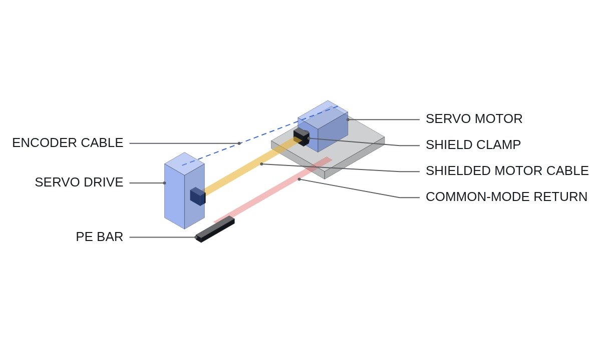
The three phase voltages of a PWM inverter output do not sum to zero, and the common-mode voltage steps with every switching event. The steep dv/dt of that voltage charges and discharges the parasitic capacitances between the motor cable conductors and the shield, and between the motor windings and the frame, which drives common-mode current. That current must return to the drive, and if the designer does not assign a path, it takes whatever path has the lowest impedance.
Many field symptoms such as “encoder errors appear only when another axis starts” or “the analog input jitters” are return-path problems. When a shield is terminated with a pigtail (shield braid twisted and landed on a terminal), a few centimetres of wire act as inductance at high frequency, the shield stops working as a return path, and the current comes back from the motor frame through the machine structure.
One practical judgement follows. Judge a noise measure not by which part was installed but by how much it reduced the loop area of the common-mode current. Add a filter without reducing the loop area, and whatever the filter does not absorb still flows through the same detour.
Design checklist
- □ Use shielded motor cable and terminate the shield with 360-degree clamps at both the drive end and the motor end. No pigtail terminations.
- □ Use an unpainted, plated steel back plate, and bond the drive, filter and clamp rail to it over a wide area.
- □ Use the PE conductor inside the motor cable together with the shield, and confirm that PE and shield connect to the motor frame with short links in the terminal box.
- □ Run power cables (input and output), control cables and encoder cables in separate ducts, crossing at right angles. Follow the drive manufacturer’s installation guide for separation distances.
- □ Place the EMC input filter near the panel entry, and do not run the filter’s input and output cables side by side in the same duct.
- □ Use a dedicated shielded encoder cable and terminate its shield as the drive manufacturer specifies.
- □ Reference the analog signal 0 V to earth at one point only, and clamp the shield at the panel entry.
- □ If measures are still needed, consider an output reactor, then a dv/dt filter, then ferrite cores, measuring before and after each step.
Comparison of measures
| Measure | What it reduces | Caution |
|---|---|---|
| 360-degree shield clamp | Common-mode return impedance | Lost on painted surfaces or pigtails |
| Input EMC filter | Conducted noise out to the supply | More PE leakage, RCD coordination |
| Output reactor | dv/dt, cable charging current | Voltage drop, heating |
| dv/dt filter | Voltage rise rate, motor insulation stress | Limited common-mode reduction |
| Sine-wave filter | Output voltage waveform itself | Size and cost, affects servo response |
| Ferrite core | High-frequency common-mode current | Effect collapses when saturated |
| Cable separation | Coupling from power to signal lines | Cheap only at the design stage |
The top two rows and the last row cost almost nothing, while the rows in the middle add size and cost and can affect servo performance. So apply measures in order of cost, not in the order of the table: finish shield termination and cable separation first, then look at filters. A sine-wave filter in particular can interfere with the servo control bandwidth, so confirm its applicability with the drive manufacturer.
PLC logic that helps measurement: an oscilloscope trigger
The hardest part of intermittent noise is catching the moment on a scope. The PLC already knows the encoder error counters and axis states, so a digital output that fires an external trigger to the oscilloscope when the error counter increments captures the waveforms around the event. The example below uses drive diagnostics mapped over ETHERCAT.
(* Scope trigger for noise diagnosis - IEC 61131-3 ST *)
(* Monitoring and diagnosis only. STO and EMO are hardwired circuits, unrelated to this logic *)
VAR
  DI_SERVO_X_READY       AT %I1.0  : BOOL;  (* X-axis drive ready *)
  DI_SERVO_Y_ENABLED     AT %I1.1  : BOOL;  (* Y-axis servo on - suspected interfering axis *)
  DI_SERVO_X_STO_ACTIVE  AT %I1.2  : BOOL;  (* X-axis STO active - monitoring only *)
  AI_X_ENC_ERR_CNT       AT %IW110 : INT;   (* X-axis encoder comm error count, ETHERCAT PDO *)
  AI_X_FOLLOW_ERR        AT %IW112 : INT;   (* X-axis following error, pulses *)
  DO_SCOPE_TRIG          AT %Q1.0  : BOOL;  (* Oscilloscope external trigger, 24 V *)
  DO_NOISE_ALARM         AT %Q1.1  : BOOL;  (* Suspected noise alarm *)
  ENC_ERR_PREV                     : INT;
  EVT_WITH_Y_ON                    : INT;   (* Events while Y-axis servo on *)
  EVT_WITH_Y_OFF                   : INT;   (* Events while Y-axis servo off *)
  TP_TRIG                          : TP;    (* Trigger pulse width *)
END_VAR

(* Trigger only on the scan where the error counter increased *)
TP_TRIG(IN := DI_SERVO_X_READY AND (AI_X_ENC_ERR_CNT > ENC_ERR_PREV), PT := T#10MS);
DO_SCOPE_TRIG := TP_TRIG.Q;

(* Count events separately by the state of the suspected axis - for correlation *)
IF AI_X_ENC_ERR_CNT > ENC_ERR_PREV THEN
  IF DI_SERVO_Y_ENABLED THEN
    EVT_WITH_Y_ON := EVT_WITH_Y_ON + 1;
  ELSE
    EVT_WITH_Y_OFF := EVT_WITH_Y_OFF + 1;
  END_IF;
END_IF;
ENC_ERR_PREV := AI_X_ENC_ERR_CNT;

(* Alarm only. Axis stop decisions are left to the drive's own protection *)
DO_NOISE_ALARM := (EVT_WITH_Y_ON + EVT_WITH_Y_OFF) > 0;
This logic does not diagnose the cause. If events cluster while the Y axis is servo-on, that only gives a reason to suspect the Y-axis motor cable return path first. The diagnosis itself comes from the common-mode current (high-frequency CT) and signal waveforms captured by the trigger. Note the limitation too: phenomena shorter than the scan time can be missed this way.
Boundary conditions
There are cases where this order does not fit. First, if the motor is very close to the drive and the shield termination is already correct but the symptom remains, the cause may not be the common-mode return at all. It may be momentary voltage dips on the supply side, communication cable specification or termination resistors, or a faulty encoder. Repeating shield work there wastes time. Second, if an existing machine was cabled with unshielded cable and re-cabling is impractical, an output-side filter becomes the realistic first measure. The single decision rule: if a high-frequency CT measures common-mode current in the PE and machine frame, start with return-path design; if it does not, investigate the supply, communication and encoder side first.