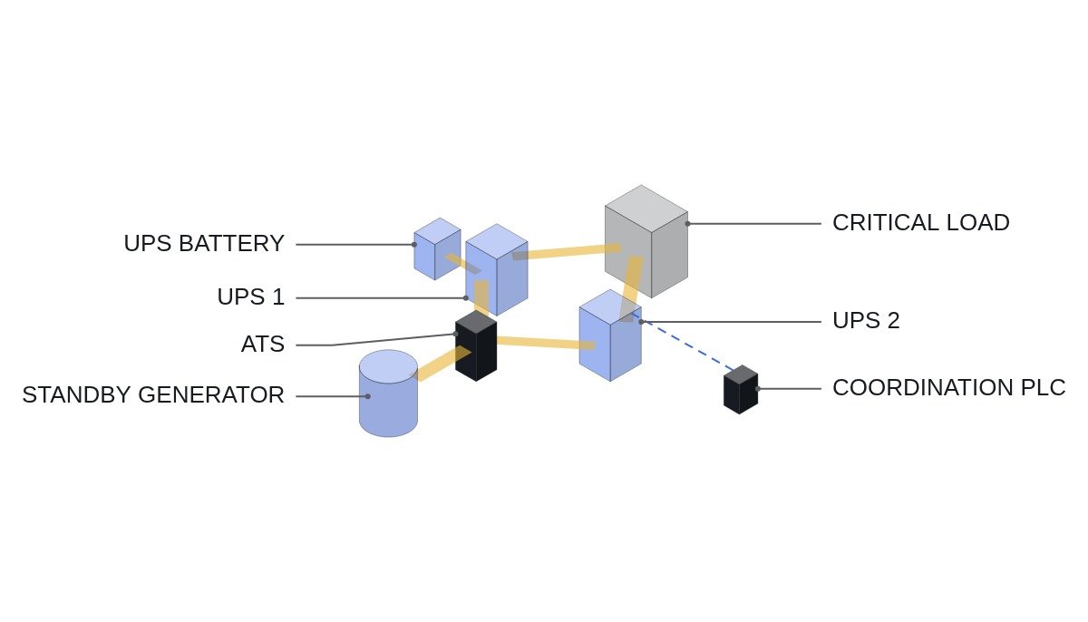
Bottom line first. Coordination between a standby generator and a UPS is not settled by “how many seconds does the generator take to start”. Where coordination actually breaks on site is usually the interval when the generator is already running but the UPS will not accept its power. If the UPS input frequency window, the rectifier walk-in and the battery recharge current do not mesh with the generator’s transient response, the UPS rejects the generator and keeps discharging its battery. Battery backup time must cover not one normal start but one failed start attempt plus this rejection interval.
Safety interlocks first — checking order for the generator–UPS link
- EMO is hardwired directly into the UPS and generator output breaker circuits. The PLC only reads EMO status.
- Shutdowns from the generator’s own protection (overspeed, low oil pressure, high coolant temperature and so on) are carried out by the generator controller. The upstream PLC does not ignore them or override them with a restart command.
- The generator start command has a second path directly from the ATS controller’s outage-detection contact, independent of the PLC. A stopped supervisory PLC must not stop the generator from starting.
- Simultaneous closing of the ATS utility and generator sides is blocked by mechanical and electrical interlocks.
- Generator room supply/exhaust dampers and the fuel supply valve are included in start confirmation, with an alarm on abnormality. Whether to block the start or only alarm in an emergency is decided in advance under the facility’s safety criteria.
- Monitor UPS battery breaker open status. In that state there is no energy to ride through the generator start.
From outage to generator pickup — defined on a time chart
Settings differ from site to site, so the safe approach is to define each interval as a variable in the order below and fill in actual values.
- t0: utility outage. The UPS goes to battery without interruption.
- T1: ATS outage confirmation delay, so the generator does not start on a momentary dip.
- T2: from cranking to established voltage and frequency. After a failed start, the generator rests and cranks again; the number of retries is a generator controller setting.
- T3: ATS transfer.
- T4: time for the UPS to judge input voltage and frequency as within tolerance.
- T5: rectifier walk-in. While the rectifier gradually takes over the load, the battery carries the rest.
As reference times for emergency systems, NEC Article 700 requires emergency power within 10 seconds, and the NFPA 110 Type 10 classification is also based on 10 seconds. But those 10 seconds are a generator-side target, not the moment the UPS accepts the generator. The required UPS battery backup time is set as follows.
- T_REQ = T1 + (one cranking period + rest) × one retry + T2 + T3 + T4 + T5 + margin
- Check that the battery meets this T_REQ using end-of-life capacity and the installation ambient temperature. Calculating from nameplate capacity alone leaves it short at end of life.
Three ways a UPS rejects the generator
First, the frequency window. At each load step the generator slows down and its frequency swings. If the UPS input tolerance is set narrow, the frequency dip at the start of rectifier pickup sends the UPS back to battery; the unloaded generator recovers frequency, and the UPS tries to pick up again. While this repetition (hunting) continues, the battery keeps draining.
Second, simultaneous pickup. If several UPS units start walk-in on the same generator at the same moment, the load steps add up at the generator. The pickup start times must be staggered unit by unit.
Third, recharge current. Right after pickup, the UPS draws the recharge power of its discharged battery on top of the load. Assumption: with a 400 kW load and 95 % UPS efficiency, input is 400 / 0.95 ≈ 421 kW, plus the recharge power. If the UPS has a function to limit charge current while on generator, use it linked to a generator-running signal.
There is one more. In normal operation the UPS inverter stays synchronized to the bypass source, but if the generator frequency leaves the sync tolerance, the inverter drops sync and runs at its own frequency. In that state it cannot transfer to static bypass on overload or inverter failure. While on generator, the UPS’s last safety net — the bypass — may effectively be unavailable, and the operating procedure must reflect that.
Generator–UPS coordination monitoring (ST pseudocode)
(* I/O MAP *)
(* %I1.0 DI_EMO_CHAIN_OK     : EMO hardwired chain healthy - status monitoring only *)
(* %I1.1 DI_GEN_ON_LOAD      : ATS generator side closed 52a *)
(* %I1.2 DI_UPS1_ON_BATT     : UPS1 on battery *)
(* %I1.3 DI_UPS2_ON_BATT     : UPS2 on battery *)
(* %I1.4 DI_UPS1_WALKIN_DONE : UPS1 rectifier pickup complete *)
(* %I1.5 DI_UPS1_BYP_SYNC    : UPS1 synchronized to bypass *)
(* %Q1.0 DO_UPS1_INPUT_EN    : UPS1 rectifier pickup enable *)
(* %Q1.1 DO_UPS2_INPUT_EN    : UPS2 rectifier pickup enable - after UPS1 completes *)
(* %Q1.2 DO_GEN_MODE_TO_UPS  : generator-running signal - linked to charge current limit *)
(* %Q1.3 DO_GEN_REJECT_ALM   : generator rejected alarm *)
(* %Q1.4 DO_BYP_UNAVAIL_ALM  : bypass out of sync alarm *)

DO_GEN_MODE_TO_UPS := DI_GEN_ON_LOAD;

(* 1. staggered pickup - UPS1 first, settle, then UPS2 *)
TON_STAGE1(IN := DI_GEN_ON_LOAD, PT := T#5S);            (* example *)
DO_UPS1_INPUT_EN := TON_STAGE1.Q;
TON_STAGE2(IN := DI_UPS1_WALKIN_DONE, PT := T#10S);      (* example *)
DO_UPS2_INPUT_EN := TON_STAGE2.Q;

(* 2. still on battery after generator closed = rejection *)
TON_REJECT(IN := DI_GEN_ON_LOAD AND (DI_UPS1_ON_BATT OR DI_UPS2_ON_BATT),
           PT := T#60S);                                  (* T4+T5+margin - example *)
DO_GEN_REJECT_ALM := TON_REJECT.Q;

(* 3. bypass out of sync on generator - no bypass on overload *)
DO_BYP_UNAVAIL_ALM := DI_GEN_ON_LOAD AND NOT DI_UPS1_BYP_SYNC;

(* EMO chain abnormal is indicated only - tripping is done by hardwiring *)
X_EMO_STATUS_ALM := NOT DI_EMO_CHAIN_OK;
A pickup enable input such as DO_UPS1_INPUT_EN is not available on every UPS, and its name and behaviour vary by manufacturer. Without it, staggered pickup is achieved by giving each unit a different walk-in delay setting in the UPS itself. The real cause of hunting is the overlap between governor response and UPS input judgment, so settings alone cannot settle it; it requires waveform analysis and field measurement of frequency during load steps.
Coordination failure modes
| Failure mode | Symptom | What to check |
|---|---|---|
| Failed start | Battery exhausted during retry | Backup time including one retry |
| Out of frequency window | UPS picks up, drops back, repeats | UPS input tolerance, governor response |
| Simultaneous pickup | Sharp generator frequency dip | Staggered pickup per UPS |
| Recharge current | Generator overload | Charge limit on generator |
| Bypass out of sync | Load drops on overload | Sync tolerance, procedure |
| Rectifier harmonics | Generator voltage distortion | Requires waveform analysis and field measurement |
Of the six rows, only the first is solved by backup time. For the rest, more battery only buys time; it does not clear the rejection. Answering a coordination problem with more battery postpones the cause, and the cause only shows up in a live-load generator pickup test during commissioning.
Commissioning checklist
- □ Was a real outage created by opening the utility breaker, and was each interval recorded from t0 to UPS pickup complete?
- □ Was a failed generator start simulated (fuel cut or another manufacturer-approved method) and the retry interval measured?
- □ Do the pickup times of multiple UPS units avoid overlapping?
- □ Is the minimum generator frequency at pickup inside the UPS input tolerance?
- □ Was UPS bypass sync status checked while on generator, and are the operating limits for the out-of-sync state in the procedure?
- □ Was battery backup time recalculated on end-of-life capacity?
- □ Was it confirmed that the generator starts with the supervisory PLC stopped?
Boundary conditions — when coordination problems vanish and when they grow
Where the generator is comfortably larger than the UPS input and the UPS has an active front-end rectifier with a smooth pickup, the rejection paths above rarely show. The design variable then is essentially battery backup time alone.
Conversely, where the generator is sized close to the UPS input, or several UPS units and motor loads share one generator, the likelihood of rejection and hunting rises. The oversizing margin for UPS load when selecting a generator is something to set from manufacturer guidance and measurement, not a general figure.
The single decision rule: if every UPS leaves battery operation on its first pickup attempt in a live-load generator test, manage backup time only; if even one drop-back is observed, fix pickup sequencing and input tolerance first, not the battery.