Bottom line first. The memorandum of understanding between ABB and Rolls-Royce SMR is exploratory cooperation, not a contract, but it is worth reading as a case study in how electrical and I&C scope should be divided in a factory-built nuclear plant. In a design where 90% of the modules are built in a factory, it pays to turn non-safety electrical packages such as motor drives, switchgear and balance-of-plant automation into standard items that can be built repeatedly. Grid interconnection interfaces and safety-class I&C, however, are tied to country- and site-specific requirements and gain little from standardization, so the most realistic design draws the standardization boundary at “non-safety systems inside the generator terminals.”
What was reported
On September 8, World Nuclear News reported that ABB signed a memorandum of understanding with UK-based Rolls-Royce SMR. ABB will examine how its automation, electrification, and instrumentation and communication solutions can support SMR deployment and scale-up, working through its UK operations in Warrington.
The article gives the Rolls-Royce SMR at 470 MWe, enough to power about one million UK homes for 60 years. The module size is 16 m by 4 m, with 90% built in a factory and 10% assembled on site.
Projects were summarized too. In October 2024 ČEZ selected Rolls-Royce SMR for up to 3 GW of deployment in the Czech Republic, with Temelín, site of an existing nuclear plant, as the primary site and coal-fired plant sites such as Tušimice as candidates. In the UK, Wylfa on Anglesey in North Wales is the designated site, with three initial units and potential for up to eight, and a final investment decision expected in 2029.
Standardization scale in unit count
Converting the reported figures to units: the Czech maximum of 3 GW ÷ 470 MWe ≈ 6.4, or around six units. Wylfa’s initial three units total 1,410 MWe; eight units would be 3,760 MWe. If both countries’ plans materialize, the number of identical units approaches double digits, giving grounds for building a standard electrical package repeatedly.
| Item | Czech Republic (ČEZ) | UK (Wylfa) |
|---|---|---|
| Planned scale | Up to 3 GW | 3 initial, up to 8 units |
| Equivalent units | approx. 6 | 3–8 |
| Equivalent output | Up to approx. 3 GW | 1,410–3,760 MWe |
| Site | Temelín (primary), coal plant sites | Wylfa, Anglesey |
| Timeline (reported) | Selected October 2024 | FID expected 2029 |
What the table says is that even with the same reactor, the grid conditions differ. The Czech Republic and the UK both run 50 Hz grids, but their system operators and grid codes differ, so anything touching the grid, such as generator protection, excitation settings and fault ride-through requirements, has to be redesigned for each site no matter how many units are built. Standardization gains accrue fully only inside that boundary.
That Temelín, the primary Czech site, already hosts a nuclear plant also matters from an equipment perspective. An existing plant site may share some transmission connection and site infrastructure, but it also brings the task of reviewing protection coordination and station power systems for existing and new units together. Coal plant sites follow the same logic, since existing transmission connection points can be reused.
Where it wins, where it doesn’t
Current conditions
At conventional large nuclear plants, electrical and I&C work has been site-specific design and field installation. Cable pulling, switchgear installation, field termination and testing pile up late in construction and often become the critical path. Slightly different designs accumulate from plant to plant, so spares and maintenance procedures also differ by unit.
What changes with factory build
With 90% factory build, much of the electrical and I&C equipment can ship already mounted on the modules. If termination and functional testing are finished in the factory, site work shrinks to inter-module connection and integrated testing. Building the same package repeatedly makes design verification, test procedures and spares common.
The connecting logic
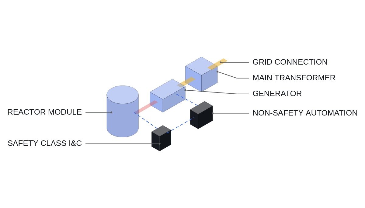
The gain from factory build comes from “moving field termination and testing into the factory.” The wider the scope that can be moved there, meaning the scope that can be designed identically regardless of site, the larger the gain. Scope whose regulatory and grid requirements vary by site, such as grid interconnection equipment and safety-class I&C, still needs site-by-site licensing and testing even if it is built in the factory.
| Equipment scope | Standardization gain | Reason |
|---|---|---|
| Auxiliary motors and drives | Large | Site-independent, repeatable |
| Non-safety automation | Large | Common control logic and HMI |
| In-plant distribution | Medium | Similar house loads, site-specific supply entry |
| Safety-class I&C | Small | National licensing and classification |
| Grid connection, generator protection | Small | Grid code per system operator |
By this table, most of the automation, electrification, instrumentation and communication scope ABB is examining falls in the upper rows. Safety-related I&C in nuclear plants is classified and separately verified under international standards such as IEC 61513 and national regulatory requirements, so it has to be designed physically and functionally separate from the non-safety standard package; otherwise standardization gains spill over into licensing burden for safety-class equipment.
Checks at the equipment design stage
- Safety-class boundary: define the signal and power interfaces between safety and non-safety systems first. Signals from the non-safety package toward safety systems pass through isolation devices.
- Protection priority: reactor protection signals must act regardless of the state of non-safety automation; confirm hardwired paths so that non-safety control cannot delay or bypass them.
- Fix the standard package scope: split the list into site-independent items (auxiliary drives, in-plant automation) and site-specific items (grid connection, generator protection).
- Factory test scope: separate items where factory functional tests can replace site tests from items that must be repeated on site.
- Communication networks: check whether plant control network zoning and cybersecurity requirements differ by country.
- Items to verify: the specific scope of the MoU and the form of supply were not disclosed.
Boundary conditions
The case for standardizing electrical and I&C reverses under the following conditions. First, when the number of units actually built falls well short of plan. If the Czech and UK programs stop at a few initial units, there is not enough repeat volume to recover development of a standard package. Second, when national regulators impose different detailed requirements even on non-safety systems, shrinking the standardizable scope even in the upper rows of the table. Third, when the MoU does not lead to a supply contract. This announcement is at the study stage, so schedule decisions that assume standardization benefits are premature.
The single decision rule is this: within the scope where repeat construction of the same design at multiple sites is confirmed, bundle only non-safety electrical and automation equipment, excluding grid interconnection and safety-class I&C, into a factory standard package.
References
- World Nuclear News, “Rolls-Royce SMR, ABB agree to collaborate”, 2026-09-08, https://www.world-nuclear-news.org/articles/rolls-royce-smr-abb-agree-to-collaborate