VOLTENERTEC WEEKLY · 2026 Week 38 · 2/5
To state the conclusion first: the Virtual Power Line (VPL) program turns ESS operation from “used like a generating asset” into “used like a transmission asset.” What actually changes on the equipment side is neither the battery nor the PCS, but command priority and interlock conditions. Equipment that used to charge and discharge for revenue optimization now receives grid-congestion-relief commands with priority, and SOC (State of Charge) operating margin rises to become an interlock input variable. Equipment whose sequence has not absorbed this shift will receive a command it cannot actually accept.
What Was Confirmed This Week, and What Was Not
The Ministry of Climate, Energy and Environment and KEPCO held a results-sharing event for the power-industry expert forum on the 17th at the KEPCO Art Center in Seoul, presenting the outcomes of eight specialist forums (116 participating experts) that ran for roughly five months after launching on April 17. Sorted by how confirmed each item is:
| Item | What Was Confirmed | Timing |
|---|---|---|
| VPL program | ₩ 2.4 billion reflected in the 2027 Ministry of Climate budget proposal | Starts next year, expansion planned through 2030 |
| Grid-forming grid code | Criteria established for centrally-contracted BESS on the transmission network to self-form voltage and frequency | Test/verification framework by November, live-grid operation in 2027 |
| Private ESS on distribution network | Technical-standard revision, field demonstration, and power-market rule improvements in parallel | In progress (schedule undisclosed) |
| AMI data integration | Revising the notice mandating KEPCO integration of AMI in new apartments | Target: MDMS integration for ~1.34 million households |
| Reflection in national grid planning | Policy to reflect VPL in the 12th Basic Plan for Electricity Supply and Demand, etc. | Dependent on planning timeline |
The line an equipment engineer should read first is the second one. The grid-forming grid code, with its test/verification framework fixed for November, reaches the field before the VPL program with its budget attached does. If 2027 live-grid operation is the target, PCS firmware and protection coordination need to be re-set to match when the test items are finalized, and that lead time is shorter than budget execution.
The Advantaged Position and the Disadvantaged Position
Under current conditions, grid congestion has been a problem solved by transmission-line expansion. When line construction is delayed for years, renewable-energy interconnection sits in a queue, while existing lines hit their limit only during peak hours and carry margin the rest of the time. From an equipment standpoint, “congestion” was a planning indicator, not an operating one.
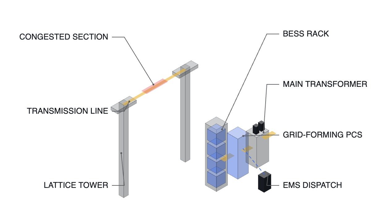
Once VPL is applied, this changes. When ESS placed at both ends of a congested section takes on the role of directly reducing line flow, congestion becomes a real-time operating indicator. Charge/discharge commands come not from market price but from line-flow constraints. The advantaged position is clear: sections where line-expansion lead time is long, congestion concentrates in specific hours, and land is available at both ends.
The disadvantaged position is equally clear. In sections where congestion persists all day, the ESS’s energy capacity runs out first. A transmission line can carry flow indefinitely within its thermal limit, but an ESS stops once its kWh is depleted. The line is a power(kW)-constrained asset, while the ESS is an energy(kWh)-constrained asset — that difference is VPL’s inherent limitation.
The chain of reasoning follows from here. As command priority shifts from market to grid, the equipment must judge for itself whether it is currently in a state to accept a command, and report that upward. The basis for that judgment is SOC margin, and that is what enters as an interlock condition.
Safety Interlock Verification Order
- Confirm that the EMO (Emergency Off) and the fire/gas detection chain open the PCS main circuit by hardwire. This path must operate independently of EMS command and communication status, and is never bypassed or delayed by software.
- Confirm the opening conditions of the DC breaker and the rack-level contactors. Cancellation of an upper-level command does not, by itself, mean physical opening — treat these separately.
- Confirm grid protection coordination. In grid-forming mode, the PCS forms voltage and frequency itself, so on a grid fault the protective-relay operating time and the PCS’s Fault Ride-Through setting must not conflict.
- Define behavior on loss of EMS communication. If command communication is lost, the unit must converge to a predefined safe state — not hold the last command.
- SOC lower/upper-limit interlock. Even if a congestion-relief command arrives, reject the discharge command when SOC is at its lower limit and report unavailability upward. The most dangerous configuration is one where that rejection is never reported upward.
- Thermal-management system status. On a cooling-system abnormality, limit output before accepting a command.
Congestion-Relief Command Acceptance Sequence (ST Pseudocode)
(* I/O MAP *)
(* DI201 : EMO AND FIRE PANEL CONTACT OK - hardwired state, read-only *)
(* DI202 : DC BREAKER CLOSED *)
(* DI203 : EMS LINK ALIVE - watchdog contact *)
(* AI201 : PACK SOC 0 - 100 % *)
(* AI202 : MAX CELL TEMP degC *)
(* AI203 : LINE FLOW MARGIN - available headroom on the congested section (MW) *)
(* DO201 : PCS DISCHARGE ENABLE *)
(* DO202 : AVAILABILITY REPORT TO EMS *)

AI_PACK_SOC := AI201;
AI_MAX_CELL_TEMP := AI202;
AI_LINE_FLOW_MARGIN:= AI203;
DI_SAFETY_CHAIN_OK := DI201;
DI_DC_BREAKER_ON := DI202;
DI_EMS_LINK_ALIVE := DI203;

(* 1. Availability judgment - available only when safety chain, breaker, thermal, and SOC margin all hold *)
B_UNIT_AVAILABLE := DI_SAFETY_CHAIN_OK
AND DI_DC_BREAKER_ON
AND (AI_MAX_CELL_TEMP < R_TEMP_LIMIT)
AND (AI_PACK_SOC > R_SOC_MIN); (* R_SOC_MIN example: 15 % *)

(* 2. Report availability upward at all times, regardless of whether a command is accepted *)
DO_AVAILABILITY_REPORT := B_UNIT_AVAILABLE;

(* 3. Congestion-relief discharge command - accept only when line-flow margin is at or below the threshold *)
IF B_UNIT_AVAILABLE AND DI_EMS_LINK_ALIVE
AND (AI_LINE_FLOW_MARGIN < R_CONGESTION_TH) THEN
DO_PCS_DISCHARGE_ENABLE := TRUE;
ELSE
DO_PCS_DISCHARGE_ENABLE := FALSE;
END_IF;

(* 4. Loss of EMS communication - do not hold the last command, converge to a defined safe state *)
IF NOT DI_EMS_LINK_ALIVE THEN
DO_PCS_DISCHARGE_ENABLE := FALSE;
B_LOCAL_SAFE_MODE := TRUE;
END_IF;
R_SOC_MIN and R_CONGESTION_TH are illustrative example values. Actual settings must be determined from the flow pattern and contract terms of the specific section, and are not values this article can finalize. What should count as the “safe state” in item 4 — a full stop, or a gradual ramp-down before stopping — is also a matter for consultation with the grid operator.
The Patent Landscape of Grid-Forming Control
Control techniques that handle grid-forming and grid-following in the same converter are already secured by a granted patent. US11108235B1, “Double synchronous unified virtual oscillator control for grid-forming and grid-following power electronic converters,” assigned to North Carolina State University, claims a Double Synchronous Unified Virtual Oscillator Control (DSUVOC) circuit. It describes a controller including double synchronous space-vector oscillation, sequence extraction, fault detection, pre-synchronization, virtual impedance, terminal-voltage compensation, and active damping elements, stating that it enables synchronization and Fault Ride-Through under both balanced and unbalanced conditions. Filed 2021-02-11, granted 2021-08-31, with rights also recorded as assigned to the U.S. National Science Foundation as of 2022-03-01.
This claim content implies one practical point. The hard part of grid-forming is not forming steady-state voltage and frequency, but staying synchronized through unbalanced fault conditions. The test/verification framework due by November is likely to concentrate its checks on exactly this.
Boundary Conditions — When VPL Turns Disadvantageous
The advantage of VPL reverses under three conditions.
First, congestion duration. If congestion is limited to a few hours a day, the ESS’s energy capacity can cover it, but in a section with persistent all-day congestion, VPL cannot substitute for line expansion. In that case VPL is not an alternative to expansion but a bridge until expansion is complete.
Second, the liability boundary on failure. If ESS is operated like a transmission asset, a drop in its availability becomes a grid constraint. What would simply be “skip it” for a generating asset becomes a constraint violation for a transmission asset. How availability guarantees and reserve-margin arrangements are reflected in the contract is not covered in what has been disclosed so far — left as an item requiring confirmation.
Third, protection coordination. Grid-forming mode’s fault-current contribution differs from that of a synchronous machine. Deploying a grid-forming PCS while leaving existing protective-relay settings unchanged can cause mis-operation or failure to operate. This requires waveform analysis and field measurement on an equipment-by-equipment basis, and should not be judged from documented standards alone.
The single selection criterion is therefore set as follows: VPL is advantageous over line expansion only when congestion concentrates in specific hours, energy capacity (kWh) sufficient to cover those hours is secured, and protection settings for the section can be re-tuned. If even one of the three does not hold, moving up the expansion schedule is the better choice.
Source: Electric Times article (in Korean), September 17, 2026