Bottom line first. Choose a battery thermal management method by the size and duration of cell heat generation and by the cell-to-cell temperature spread you can tolerate. Low C-rate ESS with small, slow heat loads can run on air cooling; assets that generate a lot of heat through fast charging or high-power duty default to liquid cooling through cold plates (indirect liquid cooling). Refrigerant direct cooling removes the secondary coolant loop and with it some thermal resistance and components, but it creates temperature spread along the evaporator path and ties the battery to the HVAC system in both hardware and control, so it mainly wins in passenger EVs where the cabin HVAC and the battery share one refrigeration cycle.
Where it wins, where it doesn’t
Current condition
Thermal management is often summed up in one line: “air is cheap, liquid performs better”. Two things are missing from that summary. One is that the heat-carrying capacity of the media (air, coolant, refrigerant) differs by thousands of times. The other is that the medium warms up as it passes the cells, and that warming itself creates cell-to-cell temperature spread.
After the change
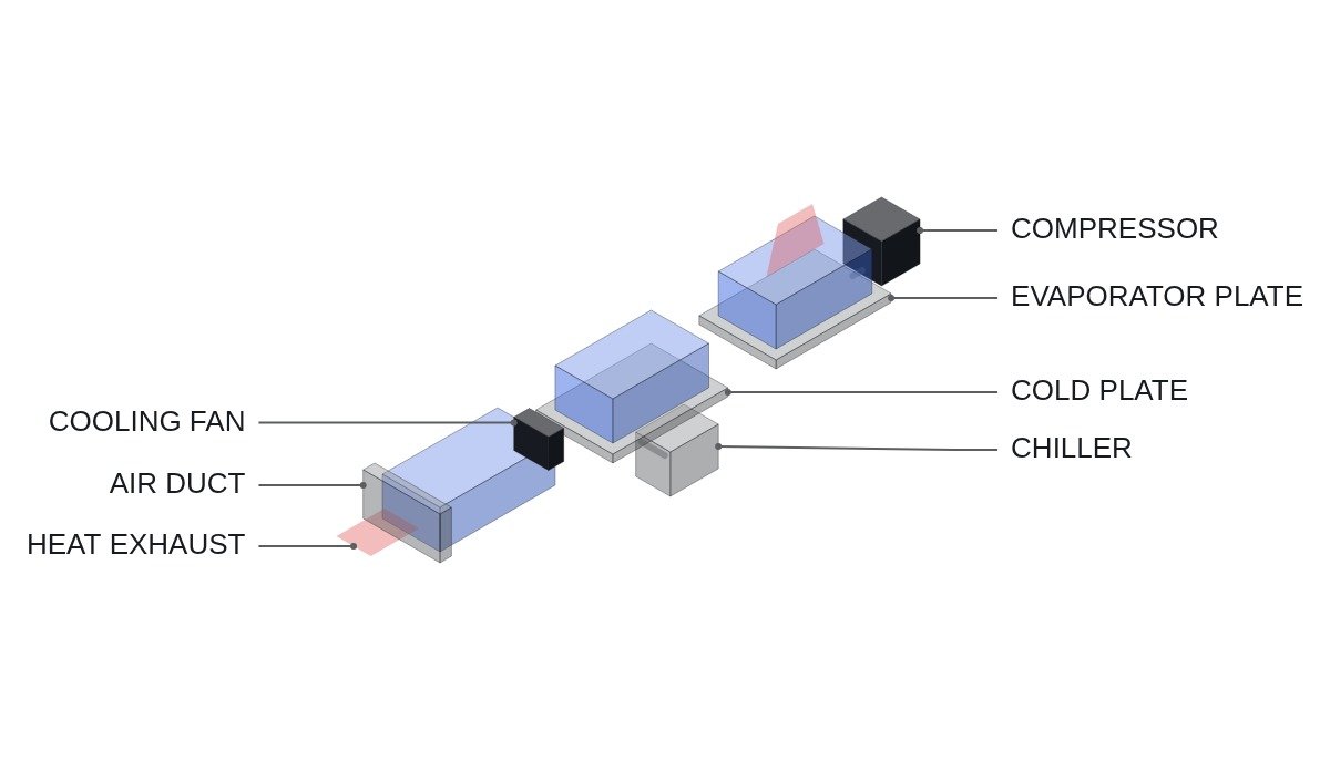
Heat transport is Q = mass flow x specific heat x temperature rise. To remove the same heat with the same temperature rise, air, with low specific heat and density, needs an enormous volumetric flow, while water-based coolant needs only a small flow. Refrigerant direct cooling uses latent heat of evaporation, so it absorbs heat almost isothermally in the evaporating section. The choice becomes a question of both heat-removal capacity and the spread created in the process.
Connecting logic
Cell-to-cell temperature spread becomes ageing-rate spread, ageing-rate spread accumulates as capacity spread, and that eventually returns as a balancing and usable-capacity problem. The real performance metric of a thermal management method is not peak temperature but the cell-to-cell temperature spread accumulated over life. In air cooling, the temperature rise from inlet to outlet becomes cell spread directly; in liquid cooling, flow can be raised to keep coolant temperature rise small; in direct cooling, the evaporating section is even but cells sitting in the superheat section run warmer.
Heat transport, calculated
Assumptions: pack (or rack) heat 5kW, medium temperature rise 5K. Water specific heat 4.18kJ/kg·K and density 1,000kg/m³; air specific heat 1.005kJ/kg·K and density 1.2kg/m³. Real coolant is a water-glycol mix with lower specific heat than water, so it needs more flow.
| Medium | Mass flow | Volume flow | Volumetric heat capacity |
|---|---|---|---|
| Air | about 0.995kg/s | about 2,990m³/h | about 1.2kJ/m³·K |
| Water | about 0.239kg/s | about 14.4L/min | about 4,180kJ/m³·K |
Mass flow is 5,000W / (specific heat x 5K). Volumetric heat capacity is specific heat x density, and water’s is about 3,500 times that of air. Removing the same 5kW with air means blowing roughly 3,000m³ per hour, which requires duct cross-section inside the pack for that airflow plus fan power. The limit of air cooling arrives first not in cooling performance but in the space to distribute that airflow evenly between cells, and in noise and fan power.
Method comparison
| Item | Air | Liquid (indirect) | Refrigerant direct |
|---|---|---|---|
| Heat carrier | Air | Water-glycol | Refrigerant (latent heat) |
| Suited heat load | Small, slow | Large, fast charging | Large |
| Source of cell spread | Air inlet-outlet delta | Coolant temperature rise | Evaporator superheat section |
| Preheating | Air heater | Same loop can heat | Separate heating path needed |
| Auxiliary power | Fans | Pump plus chiller | Compressor (shared with HVAC) |
| Leak risk | None | Coolant leak, insulation loss | Refrigerant leak |
| Condensation | Humidity dependent | Coolant temperature control | Watch at low evaporating temperature |
The rows that separate the methods are preheating and auxiliary power. Cold fast charging requires warming the cells first; liquid cooling does it by feeding heater or heat-pump heat into the same coolant loop, while direct cooling needs a separate path. In ESS, auxiliary power goes straight into round-trip efficiency, so the hotter the site over the year, the more the auxiliary power difference between methods decides operating cost.
Auxiliary power becomes tangible when converted to annual energy. Assumption: an average 10kW of thermal management auxiliary load running year-round (8,760h) is 87,600kWh a year. If the same asset discharges 1MWh once a day, that is about 24% of its annual 365,000kWh throughput spent on thermal management. The numbers are assumed, but they show why a cooling comparison cannot stop at capital cost. Part-load efficiency of fans, pumps and chillers, and operating hours by ambient condition, must be filled in with measured data for the comparison to hold.
Decision sequence
- Derive cell heat (W) and its duration from the operating profile. Start with the I²R approximation and correct it with measurement.
- Set the allowable cell-to-cell temperature spread. Use the cell maker’s recommended range if one exists.
- Compute the required flow for each method as above, and check whether duct area and fan power (air) or pump and chiller capacity (liquid) fit the installation space and supply capacity.
- If cold charging is part of operation, make the preheating path a condition of the method choice.
- For liquid and direct cooling, confirm the insulation-loss path in case of a leak, and wire leak detection and high-voltage disconnection as hardwired protection.
- Convert auxiliary power to annual energy and include it in round-trip efficiency.
Step 5 must be met regardless of the method chosen. Where coolant or refrigerant passes near high-voltage parts, a leak can lead directly to insulation loss and ground faults, so leak detection and disconnection are built as a hardwired protection path, not left to software judgment alone. Changes in insulation monitoring values are an indirect signal of leaks, so log them as a trend.
Boundary conditions
This judgment reverses under the following conditions. First, if site ambient temperature is close to the cell’s allowable temperature, air cooling fails even with small heat loads because there is no temperature margin. There, ambient conditions, not heat load, call for liquid cooling and a chiller. Second, in assets such as ESS where HVAC is separate from the battery, the core benefit of direct cooling, sharing the HVAC cycle, disappears and the case for it weakens. Third, when cold-plate contact area is small for the cell shape (curved cells, for example), internal cell temperature gradients grow even with liquid cooling, so the contact structure must be judged before the method. Fourth, uneven flow distribution and actual cell temperature distribution can differ from design calculations, so prototype measurement is a prerequisite.
Fifth, a change in operating profile changes the judgment. If an ESS that began with one slow discharge per day switches to short, large, repeated power duty such as frequency regulation, cell heat rises sharply and an air-cooled design can hit its limit. If the operating mode may change during asset life, leaving margin in initial thermal capacity, or reserving space and piping routes to upgrade cooling later, lowers total cost. Conversely, oversizing cooling for an asset with a fixed duty only adds auxiliary power.
The single selection rule: if peak operating heat can be removed by airflow while keeping cell-to-cell temperature spread within limits, air cooling wins; if not, liquid cooling wins; and direct refrigerant cooling goes on the list only when the battery and HVAC share one refrigeration cycle.