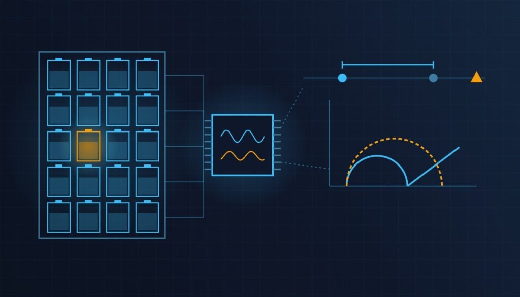
The conclusion first. The safety interlock for insulation resistance and dielectric withstand (hipot) testing on a battery module EOL (End of Line) tester differs from an ordinary high-voltage tester in two ways. First, the device under test is itself a source that cannot be switched off, so a door-release condition that assumes a “de-energized state” does not hold. Second, an insulation test fails in the direction where a lost probe contact reads as infinite insulation resistance, so a defective part is judged as a pass. The interlock therefore has to include two points without exception: a contact check before high voltage is applied, and a discharge check measured at the DUT terminals after it is removed.
Safety interlock conditions first
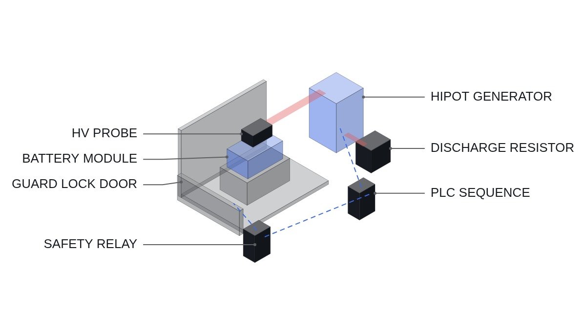
The tester’s high-voltage output may be live only under conditions where nobody can be inside the guard. The conditions below are built hardwired in the safety relay (or safety PLC) circuit; the standard PLC only monitors status and manages the test sequence.
- □ EMO is a hardwired safety circuit that directly removes power from the HV generator and opens the output relay. The PLC reads EMO status as a monitoring input only.
- □ The guard door uses guard locking. The HV enable contact closes only when the locked-confirmation signal reaches the safety relay.
- □ A door unlock request is passed to the safety relay only after the discharge-confirmed condition holds. Discharge is confirmed by voltage measurement, not by a timer.
- □ The beacon and indicator lamps during HV application are driven directly from the HV output circuit or from an output-status contact. Lamps driven by a PLC output are auxiliary only.
- □ In manual mode (probe adjustment and similar), the HV generator supply is physically isolated, and the key switch position is an input to the safety relay.
Depending on the equipment configuration, review IEC 60204-1 (electrical equipment of machines), ISO 13849-1 (safety-related parts of control systems), ISO 14119 (interlocking devices) and IEC 61010-1 (safety of measurement and test equipment) together. The required performance level (PL) comes from the risk assessment and is not fixed here.
How module testing differs from ordinary high-voltage testing
In a withstand test on ordinary electrical equipment, the object under test is unpowered. A battery module is not. From the moment cells are assembled, a DC voltage in the range of tens to hundreds of volts is always present between the module terminals, and it does not go away when the tester is switched off. The insulation test bonds the positive and negative terminals together and applies the test voltage between that bond point and the module case (chassis).
Two energies appear here. One is the module’s own voltage; the other is the terminal-to-chassis capacitance charged by the test voltage. The second is E = ½CV². Assumptions: terminal-to-chassis capacitance 100 nF, DC test voltage 2,000 V, giving E = 0.5 × 100×10⁻⁹ × 2,000² = 0.2 J. With a 1 MΩ discharge resistor, τ = RC = 0.1 s, and falling below 1% takes about 4.6τ ≈ 0.46 s. Actual capacitance and discharge path resistance vary by module and must be measured.
This is why the discharge measurement point matters. Open the tester output relay first and the tester-side voltmeter reads zero, while the DUT-side capacitance loses its discharge path and holds its voltage. Discharge with the probe still attached, and confirm at the DUT terminals.
Comparison by test type
| Item | Insulation (IR) | DC hipot | AC hipot |
|---|---|---|---|
| Pass criterion | Minimum resistance | Maximum leakage | Maximum leakage |
| Capacitance effect | Needs settling after charge | Leakage only after charging current | Capacitive current adds to leakage |
| Residual charge | Yes | Yes (discharge required) | Depends on cut-off phase |
| Result on lost contact | False pass | False pass | False pass |
| Recommended order | First | After IR pass | After IR pass |
That the “result on lost contact” row is identical for all three methods is the core risk of this equipment. Whatever method is chosen, a test applied without a contact check can pass a defective module. Running IR first to screen out weak insulation also reduces equipment damage from breakdown during the hipot step.
Test sequence and PLC logic
Time chart premise: t0 door closed and locked, t1 contact check (module voltage measured through the probe, then the terminal bonding relay closes), t2 IR test, t3 hipot ramp-up and hold, t4 ramp-down, t5 discharge relay closes, t6 discharge confirmed by DUT terminal voltage, t7 output relay opens, t8 door unlock request.
(* I/O MAP
   %I2.0  DI_EMO_LOOP_OK        : EMO hardwired loop healthy (monitor only)
   %I2.1  DI_GUARD_LOCKED       : guard door closed and locked (safety relay status)
   %I2.2  DI_SAFETY_RELAY_OK    : safety relay output healthy
   %I2.3  DI_HV_OUTPUT_ACTIVE   : HV output active contact from tester
   %IW300 AI_DUT_PACK_V         : module terminal voltage via probe, 0.1 V/digit
   %IW302 AI_DUT_CHASSIS_V      : DUT terminal-to-chassis voltage, 1 V/digit
   %Q2.0  DO_HV_ENABLE_REQ      : HV enable request to safety relay (not the enable itself)
   %Q2.1  DO_DISCHARGE_RELAY    : discharge relay close (probe still attached)
   %Q2.2  DO_HV_OUT_RELAY       : tester output relay close
   %Q2.3  DO_DOOR_UNLOCK_REQ    : unlock request to safety relay
*)
VAR
  CONTACT_OK   : BOOL;   (* latched at step 10, before terminals are bonded *)
  DISCH_DONE   : BOOL;
  T_DISCH_MIN  : TON;    (* minimum discharge time, sized from measured RC *)
  STEP         : INT;    (* 0 idle, 10 contact check, 20 IR, 30 HV ramp/hold,
                            50 discharge, 60 discharge confirmed, 70 output open *)
END_VAR

(* contact check at step 10: probe must read module voltage inside expected window;
   terminal bonding relay closes only after this check *)
IF STEP = 0 THEN CONTACT_OK := FALSE; END_IF;
IF STEP = 10 THEN
  CONTACT_OK := (AI_DUT_PACK_V > PACK_V_MIN_SP) AND (AI_DUT_PACK_V < PACK_V_MAX_SP);
END_IF;

(* HV request only when guard locked, safety relay healthy, EMO loop healthy, contact OK *)
DO_HV_ENABLE_REQ := DI_EMO_LOOP_OK AND DI_GUARD_LOCKED AND DI_SAFETY_RELAY_OK
                    AND CONTACT_OK AND (STEP >= 20) AND (STEP < 50);

(* discharge through probe: output relay stays closed while discharging *)
DO_DISCHARGE_RELAY := (STEP >= 50) AND (STEP < 70);
T_DISCH_MIN(IN := DO_DISCHARGE_RELAY, PT := T#1S);   (* example, from 4.6 tau plus margin *)
DISCH_DONE := T_DISCH_MIN.Q AND (ABS(AI_DUT_CHASSIS_V) < SAFE_V_SP);
IF STEP = 50 AND DISCH_DONE THEN STEP := 60; END_IF;  (* measured, not timer alone *)
DO_HV_OUT_RELAY := (STEP >= 10) AND (STEP < 70);

(* unlock request only after measured discharge at DUT side; timer alone never unlocks *)
DO_DOOR_UNLOCK_REQ := (STEP >= 60) AND DISCH_DONE AND NOT DI_HV_OUTPUT_ACTIVE;
In the code, DO_HV_ENABLE_REQ is only a request; the actual HV enable is decided by the safety relay contact in series with the DI_GUARD_LOCKED condition. SAFE_V_SP and the minimum discharge time are set from the module’s measured capacitance and discharge resistance, and re-measured whenever the module type changes.
Field verification checklist
- □ Is the probe contact check a window comparison (upper and lower limit) on the measured module voltage, and does the test refuse to start outside the window?
- □ Is the discharge-confirmation measurement taken between the DUT terminals and chassis, not at the tester output?
- □ Is there feedback that detects a welded discharge relay contact? A welded contact leaks the next test’s high voltage into the discharge resistor and distorts the result.
- □ Is guard lock release routed through the safety relay, with no path where a PLC output alone releases it?
- □ Has the leakage current waveform been checked for disturbance from nearby equipment noise? Unstable results are managed as an item that requires waveform analysis and field measurement.
- □ Is there a defined quarantine location and a do-not-retest marking procedure for modules that break down?
Boundary conditions
There are conditions under which this design is wrong. First, testing a module with its BMS board or insulation monitoring circuit fitted turns that circuit into a leakage path and destabilizes the result; the process must define the disconnection condition before the test. Second, on large modules with high terminal-to-chassis capacitance, discharge time grows and collides with cycle time; lowering the discharge resistance then requires a review of the discharge element’s thermal capacity. Third, if the test object is a single cell rather than a module, capacitance and energy are small, so the order stays the same but the time settings change substantially.
The single decision rule: if the door release condition does not include “measured voltage at the DUT terminals,” the tester’s interlock is timer-based and has to be redesigned.