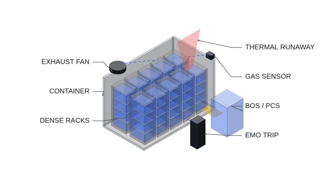
When the energy source changes, the equipment it needs changes too. In particular, the power conversion system (PCS/inverter) is designed differently depending on the characteristics of the energy source it connects to.
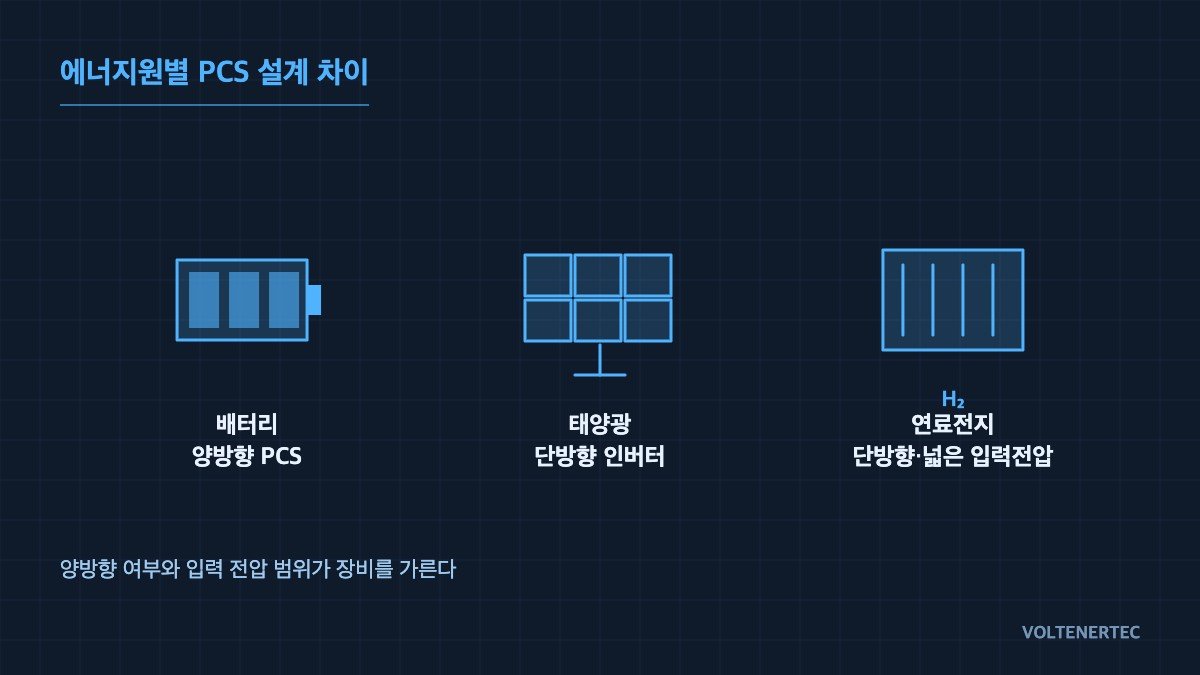
Key Equipment Differences by Energy Source
| Energy Source | Key Equipment | Design Point |
|---|---|---|
| Secondary batteries | Bidirectional PCS, BMS | Bidirectional charge/discharge control, cell protection |
| Solar | Unidirectional inverter (DC-AC) | MPPT (maximum power point tracking) efficiency |
| Fuel cells | Unidirectional converter | Handles a wide input voltage variation range |
Implication: the three rows come down to two axes. Does power flow in one direction or both, and how much does the input voltage swing? Check those two items first when reading an equipment specification, and the rest of the specification falls into place.
Why the Equipment Differs
Batteries must cycle between charging and discharging, so bidirectional conversion is essential, while solar panels only generate electricity, so unidirectional is sufficient. Ignoring this difference and trying to make equipment serve both purposes leads to efficiency losses or overdesign.
Where it wins, where it doesn’t
Where a bidirectional PCS wins. Current condition: the source alternates between charging and discharging, like a battery. After applying it: one converter reverses the power flow and handles both the charge path and the discharge path. Connecting logic: direction change is itself an operating condition, so managing mode transfer and protection inside one unit keeps the sequence simpler than coordinating two separate units from outside.
Where a bidirectional PCS loses. Current condition: the source only generates, like solar. After applying it: the equipment carries a reverse path, plus its control and protection functions, that is never used. Connecting logic: unused functions are still parts to buy, test and maintain, which is exactly where the overdesign mentioned above comes from.
Where a wide-input converter wins. Current condition: the source voltage moves considerably with operating state, like a fuel cell. After applying it: the converter stays within its operating range as the voltage swings. Connecting logic: outside its input range a converter trips on protection, so input range is an availability issue before it is an efficiency issue.
Where a solar-only inverter loses. Current condition: the site generates only at first but plans to add a battery later. After applying it: a unidirectional inverter has no charge path, so a separate battery-side converter has to be added. Connecting logic: where expansion is already planned, reviewing bidirectional capability at the initial selection stage avoids paying twice.
Character comparison of the converters
| Aspect | Bidirectional PCS | Solar inverter | Fuel cell converter |
|---|---|---|---|
| Power flow | Charge and discharge | DC-AC, one way | One way |
| Control focus | Charge/discharge mode transfer | MPPT tracking | Wide input voltage |
| Coordinates with | BMS protection signals | Panel string state | Fuel cell operating state |
| Problem if shared | Overdesign for one-way use | No charge path | Trips outside input range |
Implication: the three units differ less in conversion method than in what they must coordinate with. A bidirectional PCS cannot issue a run permit without BMS signals, a solar inverter follows the panels, and a fuel cell converter rides through voltage swings. Different coordination partners mean a different I/O map and a different interlock arrangement.
Checks before selecting equipment
- Check the safety interlock first. Confirm that the battery-side breaker status and BMS protection signals are hard-wired into the PCS run-permit condition. Hardware safety circuits such as EMO must not be replaced by software settings.
- Define the power flow direction. Confirm whether the source also receives power or only delivers it; if bidirectional, draw the charge/discharge mode transfer conditions on a time chart first.
- Compare input voltage ranges. Take the source minimum and maximum operating voltage (V) from the manufacturer data and confirm it fits the converter input range. The values are items to verify per source.
- List coordination signals at I/O map level. Specify the signals exchanged with the BMS, MPPT or fuel cell controller, the protocol (MODBUS, CAN, etc.) and the behaviour on communication loss.
- Hold field variables open. Do not assign a cause to switching noise or communication errors at the design stage; leave them on the commissioning list as requiring waveform analysis and field measurement.
Summary
Even the same “power conversion system” has different required specifications depending on the energy source it’s attached to. Equipment selection must come after first understanding the electrical characteristics of the energy source.
Boundary conditions
The case for dedicated equipment per source assumes one converter per source. If solar and battery share a DC bus, solar power also leaves through the battery-side path, so one bidirectional PCS serving both sources can reduce the number of units and conversion stages. Conversely, if each source has a different operator and protection scope, shared equipment means a single fault stops two systems at once. The single criterion is this: share a converter only when the power flow directions and input voltage ranges it must handle all fall within one unit’s operating range; if any one falls outside, split the equipment by source.
Related reading (Korean) — Core Equipment Configuration of ESS (Energy Storage Systems) — PCS, BMS, and Battery Racks