Let me state the conclusion first. The low-voltage response of data-center-scale loads is no longer a matter of protection settings inside the site; it is moving into the conditions for grid connection. The protection logic of “trip immediately when voltage wavers” is safe from the standpoint of a single facility, but the moment hundreds of sites with the same settings react simultaneously to the same waveform, from the grid’s point of view it becomes an event in which several GW of load disappears within tens of ms. The design basis has to be flipped to “ride through the defined region, and trip only outside it.”
1. What happened — 3.8 GW dropped out at once
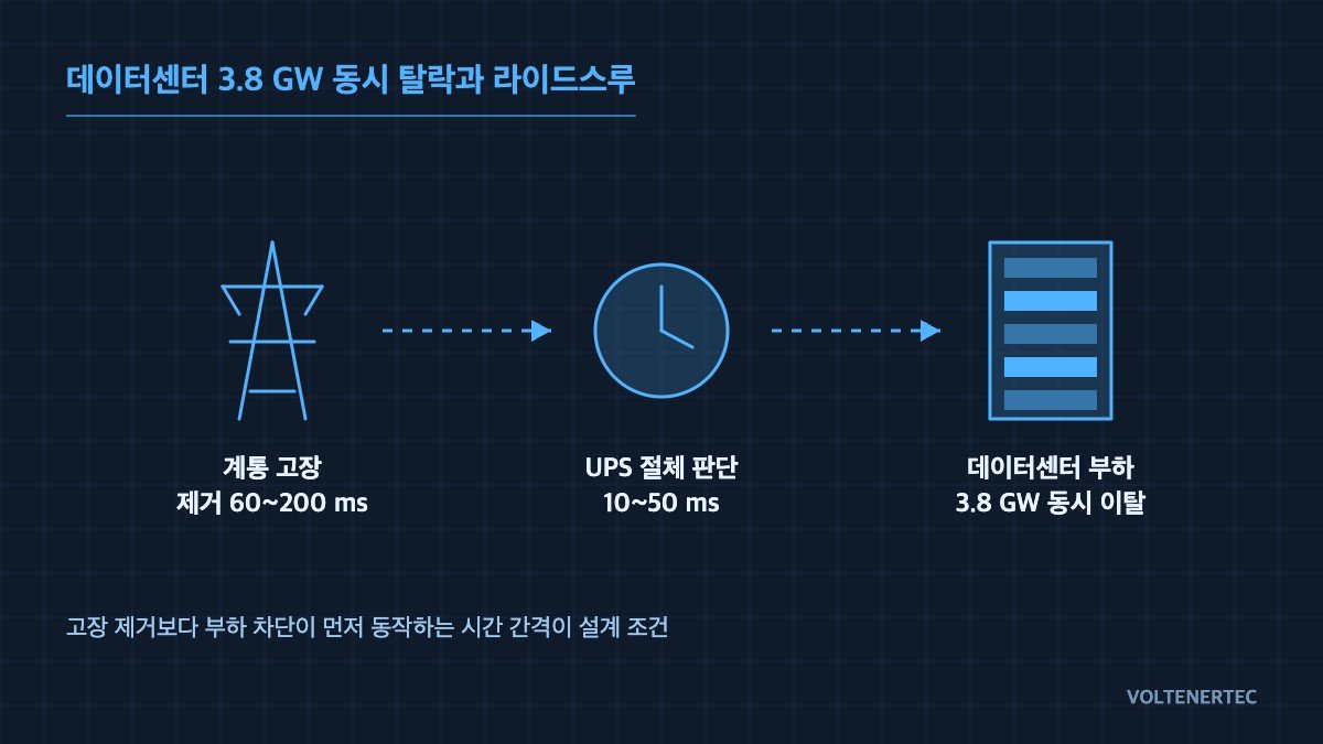
After an event in which about 3.8 GW of data center load in the Northern Virginia area dropped off the grid at once, PJM and NERC are considering introducing ride-through reliability standards for large loads. Generation-side resources are already subject to low-voltage ride-through (LVRT) requirements, but on the load side there has effectively been no mandatory requirement. This review is aimed at closing that gap.
Around the same time, Virginia regulators ordered that transmission costs caused by data centers be allocated directly to those customers. It is fair to say that connection costs are rising and connection conditions are getting stricter, both at the same time.
2. Why they drop “simultaneously” — the settings are synchronized
The structure observed in the field is simple. A data center power system runs from dual utility feeds → static transfer switch (STS) → UPS → PDU. Each UPS switches to battery mode when its input voltage leaves the specified lower limit, and some sites go further and trip the upstream breaker to separate completely from the grid.
The problem is that this decision logic tends to use similar thresholds and delay times regardless of vendor. Looked at one facility at a time, it is normal operation, but when hundreds of sites read a single fault waveform as the same signal and run the same sequence, the result is not individual protection but a grid event. From a design standpoint, it is more useful to view the essence of this case not as equipment failure but as synchronization of protection settings.
3. Fix the conditions first on an operating time chart
Because operating sequences differ from site to site, the discussion starts from a fixed time chart. Below are the typical response intervals for a 22.9 kV service entrance with a redundant UPS configuration. Actual settings vary with grid impedance and load characteristics, so waveform analysis and field measurement are required.
| Stage | Elapsed time | Action | Design decision point |
|---|---|---|---|
| Fault occurs | t = 0 ms | Grid-side single line-to-ground or two-phase short circuit, residual voltage 40-70% | Residual voltage equals the stress level on the load |
| Voltage detection | t ≈ 2-8 ms | Relay 27 (undervoltage) picks up, RMS updated every 1/4 cycle | The shorter the detection delay, the higher the probability of maloperation |
| Transfer | t ≈ 4-10 ms | STS transfer or UPS enters battery mode | Up to here, the load does not disappear from the grid |
| Load trip | t ≈ 10-50 ms | Upstream breaker trips → load leaves the grid | Making this stage conditional is what ride-through means |
| Fault clearing | t ≈ 60-200 ms | Grid protection operates, voltage recovers | Tripping before recovery leaves only losses |
There is one thing to read from this table. Most grid faults are cleared within 60-200 ms, but load tripping happens much earlier, at 10-50 ms. In other words, sites are tripping on events they could have ridden through, and this is exactly the interval regulators are trying to address.
4. Immediate-trip vs ride-through-oriented design
| Item | Immediate trip (existing) | Ride-through oriented |
|---|---|---|
| Trip decision | Immediately on undervoltage pickup | Based on residual voltage × duration curve |
| Reference basis | In-house protection settings | SEMI F47 and ITIC (CBEMA) curves, grid connection requirements |
| Example hold requirement | None | Hold about 200 ms at 50% residual, 500 ms at 70% |
| UPS battery burden | Low (immediate separation) | More shallow discharges → added life-management item |
| Grid impact | Simultaneous loss of large loads, risk of frequency rise | Load retained, limiting event propagation |
| Regulatory risk | May fail future connection conditions | No rework needed when standards are introduced |
The implication is clear. Ride-through is not a matter of buying more equipment but of rewriting settings and interlock conditions, and for a new site it adds almost no cost. Conversely, if connection conditions change after completion, protection coordination has to be reviewed and commissioning repeated.
5. Reference logic and I/O map
Below is a reference skeleton for the decision block. The premise that safety interlocks come first does not change. The EMO (Emergency Off) and protective relay trip contacts remain hardwired circuits, and the software decision must never be configured to bypass them.
(* Large-load low-voltage ride-through (LVRT) decision — reference skeleton *)
(* Finalize settings after measuring grid impedance and load characteristics *)

(* ---------- I/O MAP ---------- *)
(* %IX0.0  EMO_OK        : E-stop circuit healthy (NC contact, hardwired)      *)
(* %IX0.1  RELAY_27_PU   : Undervoltage relay 27 pickup (residual 70% or less) *)
(* %IX0.2  RELAY_50_TRIP : Instantaneous overcurrent 51/50 trip (internal fault) *)
(* %IX0.3  UPS_BAT_READY : UPS battery available (SOC above lower limit)       *)
(* %IW10   V_RESIDUAL    : Residual voltage [%], RMS updated every 1/4 cycle   *)
(* %QX0.0  CB_MAIN_TRIP  : Service entrance breaker trip command               *)
(* %QX0.1  RIDE_ACTIVE   : Ride-through in progress (notify HMI and SCADA)     *)

(* ---------- Interlock priority ---------- *)
(* Priority 1: EMO_OK = FALSE or RELAY_50_TRIP = TRUE                          *)
(*             → trip immediately, unconditionally. Always overrides ride-through. *)

IF (NOT EMO_OK) OR RELAY_50_TRIP THEN
    CB_MAIN_TRIP := TRUE;          (* Internal fault or E-stop: separate immediately *)
    RIDE_ACTIVE  := FALSE;
ELSIF RELAY_27_PU AND UPS_BAT_READY THEN
    (* Judged as external grid fault: hold trip while inside the hold curve *)
    RIDE_ACTIVE := TRUE;
    T_RIDE(IN := TRUE,
           PT := SEL(V_RESIDUAL >= 70, T#200ms, T#500ms));
    (* 50% range: 200 ms / 70% range: 500 ms — refer to SEMI F47 curve *)
    IF T_RIDE.Q THEN
        CB_MAIN_TRIP := TRUE;      (* Hold limit exceeded = sustained fault *)
    END_IF;
ELSE
    T_RIDE(IN := FALSE);
    RIDE_ACTIVE := FALSE;
END_IF;
One point deserves emphasis. The reason UPS_BAT_READY is included in the decision condition is that attempting to ride through when the battery cannot support it means the ride-through fails and the normal transfer is missed as well. The hold condition must always be tied to an energy-availability signal.
6. Field checkpoints
- Check whether the setting of the relay 27 on the service entrance panel and the UPS input lower-limit voltage have an overlapping region — if they overlap, which one acts first is unpredictable.
- Put the UPS transfer time (ms) and the upstream breaker trip delay (ms) on the same time chart and compare. If the trip is faster than the transfer, ride-through cannot work.
- Add the number of shallow battery discharges (shallow cycles) to the BMS log items. Adopting ride-through increases the cycle count.
- Keep the EMO and protective relay trip paths hardwired. Do not place them inside the software decision block.
- Record the
RIDE_ACTIVEstatus and the residual voltage waveform as events in SCADA. Once the standard is formalized, these become submission records. - When negotiating connection with the grid operator, request the “hold curve” in writing. Verbal agreements do not survive past completion.
7. Boundary conditions — where ride-through becomes a disadvantage
Ride-through is not always advantageous. If the fault is not a temporary fault on the grid side but a sustained fault, overcurrent flows into rectifier and motor loads under low voltage during the hold time, and thermal stress accumulates. The same applies when an internal site fault (cable degradation, transformer inter-turn short) is misjudged as an external fault. In these cases, the hold decision only works to increase the damage.
So the selection criterion is reduced to one rule. Set the ride-through hold time so that it does not exceed the maximum fault clearing time of upstream grid protection, and treat undervoltage lasting beyond that time as a sustained fault and trip. As long as this rule holds, contribution to the grid and equipment protection do not conflict. The moment the hold curve is set without reference to the grid protection coordination table, both objectives are lost.
References
- PJM and NERC review of large-load reliability standards — Utility Dive
- Virginia regulators order direct allocation of transmission costs — Utility Dive