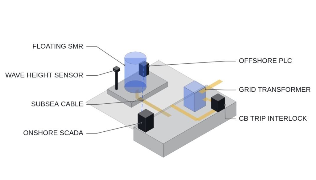
Gijang in Busan has been confirmed as the demonstration site for Korea’s i-SMR (innovative small modular reactor), and the industrial infrastructure under the SMR Special Act is taking shape (manufacturing support centers in Changwon, Busan and Gyeongju, plus a KRW 100 billion (1,000억 원) nuclear industry growth fund). At this stage, however, the detailed grid interconnection design (single-line diagram and protection coordination study) has not been made public. This article does not describe an actual project specification. It presents a pre-design checklist based on standard procedures commonly applied to SMR grid interconnection (IEEE 1547, IEC 61850). Before any real application, conditions must be reconfirmed against the operating time chart.
Safety interlocks first
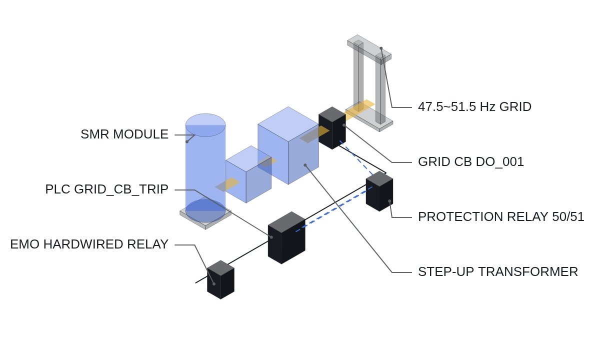
The first item to check before starting interconnection design is the independence of the EMO (emergency off) circuit. The EMO must trip the primary and secondary systems separately at the hardwired relay level, independent of the PLC logic, and no software logic may replace or bypass this circuit.
Grid interconnection interlock checklist
- Is the hardwired EMO circuit configured independently of the PLC I/O? (no software bypass)
- Is the trip sequence defined between the grid protection relays (49F over-frequency, 50/51 overcurrent) and the SMR output circuit breaker (CB)?
- Are the under-frequency (UFR) and under-voltage (UVR) protection coordination settings for grid interconnection documented according to IEEE 1547?
- Is the anti-islanding interlock for grid faults reflected in the grid-forming/grid-following transfer logic?
- Is IEC 61850 GOOSE communication redundant, and is the watchdog timeout value defined?
- Has fail-safe (hold-in-stop) behavior been confirmed for communication errors and noise? Requires waveform analysis and field measurement.
Example I/O map
| I/O address | Signal name | Type | Operating condition |
|---|---|---|---|
| DI_001 | EMO_PB_STATUS | Digital In | 0 = pressed (trip), 1 = normal |
| DO_001 | GRID_CB_TRIP | Digital Out | 1 when a grid abnormality is detected (49F/50/51 AND) |
| AI_001 | GRID_FREQ_HZ | Analog In (4-20mA) | Normal range 47.5-51.5 Hz |
| DI_010 | GOOSE_WATCHDOG | Digital In | 0 when timeout (e.g. 200 ms) is exceeded → transfer to safe state |
Actual I/O addresses for SMR grid interconnection will vary with each project’s grid impact assessment and the manufacturer’s specifications, so the table above is an example for pre-design review only.
Reference logic snippet
(* Trip logic for the SMR output breaker on grid abnormality - concept example; I/O addresses are placeholders until the project is finalized *)
IF (GRID_FREQ_HZ < 47.5) OR (GRID_FREQ_HZ > 51.5) OR (GOOSE_WATCHDOG = FALSE) THEN
    GRID_CB_TRIP := TRUE;      (* DO_001, grid separation *)
    ALARM_LOG('GRID_PROTECTION_TRIP');
END_IF;

(* Safety interlock: the EMO trips first through the hardwired relay, independent of this logic *)
(* This logic does not replace the EMO circuit; software bypass is prohibited *)
Reading the checklist as three separate layers
The six checklist items are easy to read as one list, but they belong to three different layers, and mixing them is the most common source of design errors at the interconnection stage. The first layer is the hardwired safety layer: the EMO circuit and the relay-level trip paths. It must work even when every controller and every network is dead. The second layer is the protection relay layer: frequency, voltage and overcurrent functions that decide when the output breaker opens. The third layer is the communication and supervision layer: IEC 61850 GOOSE messaging, watchdogs and alarm logging.
Each layer has a different failure mode. A hardwired circuit fails by losing a contact or a wire, and it should be designed so that this failure leads to a safe state. A protection relay fails through a wrong setting or poor coordination, which is why the settings must be documented and traced to a standard. A communication layer fails through timeouts, packet loss and noise, and its failures are the hardest to reproduce on a test bench. The example logic above sits in the third layer and only reacts to what the second layer and the network report; it never takes the place of the first.
This layering also explains why the checklist starts with the EMO. If the EMO depends on the PLC or on a network, a single failure in the third layer can disable the first, and the whole protection concept collapses into one point of failure.
Character comparison of the three layers
| Aspect | Hardwired safety | Protection relays | GOOSE / supervision |
|---|---|---|---|
| Role | Last-resort trip | Decide breaker opening | Share status, detect loss |
| Depends on software | No | Settings only | Yes |
| Typical failure | Open wire, stuck contact | Wrong setting, miscoordination | Timeout, noise, packet loss |
| How it is verified | Functional trip test | Coordination study, relay test | Communication test, field measurement |
| May override others | Yes, always | Overrides supervision | Never |
The implication is that verification effort should follow the layer, not the checklist order. A layer that depends on software and networks cannot be proven by a single commissioning test, so its fail-safe behavior has to be confirmed under real noise and communication conditions, while the hardwired layer must be proven to work with every upper layer switched off.
Pre-design review order
- Draw the EMO and hardwired trip paths on their own sheet and confirm that no PLC output or network device sits in series with them.
- List every protection function at the point of interconnection and map each one to the breaker it trips and to the standard that sets its value.
- Define the islanding scenario explicitly: what the plant does when the grid disappears, and how the grid-forming/grid-following transfer is blocked or permitted.
- Define GOOSE redundancy and the watchdog timeout, and state in writing what the logic does when the watchdog expires.
- Only after the project’s grid impact assessment and the manufacturer’s single-line diagram are issued, replace the example addresses and values with project values and run the review again.
Items to verify
- □ Final single-line diagram and protection coordination study from the project
- □ Results of the grid impact assessment for the connection point
- □ Manufacturer’s specification for the SMR output breaker and its trip coil circuit
- □ Network architecture for IEC 61850 GOOSE, including redundancy method
- □ Noise and communication error behavior on site: requires waveform analysis and field measurement
Boundary conditions
The settings and I/O addresses above are only pre-design review items based on standard procedures, and they must not be applied as they are until the actual grid impact assessment results and the manufacturer’s SLD are finalized. In particular, the GOOSE watchdog timeout and the protection coordination settings must be finalized through field measurement and waveform analysis. The layered view in this article also has a limit: if the final design places parts of the protection function inside a networked controller, the boundary between the second and third layers shifts, and the verification plan has to be redrawn around that change. The single criterion is this: before any value is fixed, confirm that the hardwired safety layer trips on its own with every software and network layer removed.
References
- SMR, a KRW 2,160 trillion market and a solution to the AI power crunch – Global Economic
- US20190206580 — SMR load-following generation patent (for reference, overseas case)