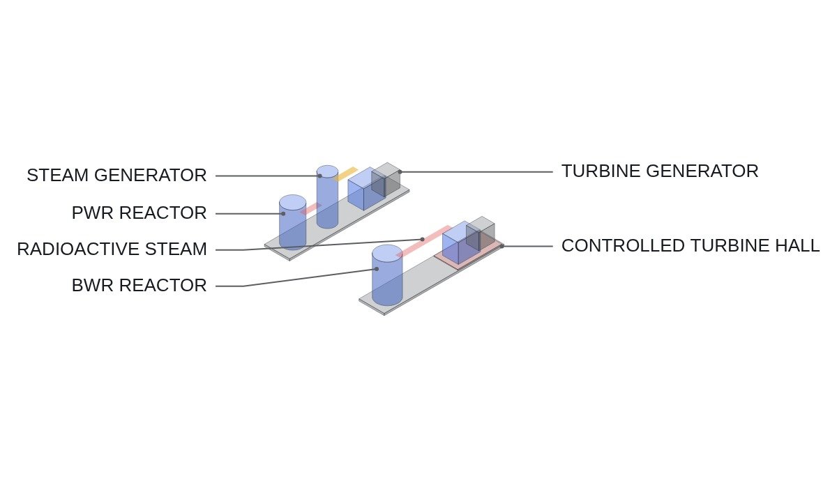
The conclusion first. Reduced to one line from an operator’s point of view, the difference between a pressurized water reactor (PWR) and a boiling water reactor (BWR) is where you draw the radiation boundary. A PWR cuts the boundary at the steam generator and keeps the turbine and generator side non-radioactive, but in exchange it takes on a high-pressure primary loop and steam generator tubes as things to manage. A BWR sends steam made in the core straight to the turbine and simplifies the plant, but it pulls the entire turbine building inside the radiation-controlled area. If maintenance labor and radiation protection capacity are the bottleneck, the PWR wins. If reducing primary-system equipment count and operating pressure comes first, the BWR wins.
Where it wins, where it doesn’t
Start with the current conditions. Both designs use light water as moderator and coolant and low-enriched uranium as fuel. The difference is where heat becomes steam. A PWR holds primary coolant at roughly 15 MPa so it does not boil in the core, and boils secondary-side water in the steam generator. A BWR boils water directly in the core at roughly 7 MPa.
Applying that structure changes operations in three main ways. First, BWR main steam carries N-16 produced as coolant passes through the core, so the turbine area needs shielding and access control during operation. N-16 has a half-life of about 7 seconds and disappears quickly after shutdown, but on-line access for turbine-side maintenance is still worse than in a PWR. Second, a PWR adds a pressurizer and steam generators, which increases primary-system equipment and the length of high-pressure boundary. Third, power is controlled differently: a PWR uses control rods and coolant boron concentration, while a BWR uses control rods and recirculation flow.
The connecting logic is this. When the radiation boundary stops in front of the turbine, maintenance on the turbine, generator, and main transformer can follow procedures similar to a conventional plant. When the boundary extends past the turbine, the condenser and feedwater systems also fall under radiation-protection procedures, adding one more constraint to every outage plan. In return, with no steam generator, the PWR-specific life-management work of tube inspection, plugging, and replacement disappears. Which burden weighs more on a given operator decides the choice.
Structure and operating characteristics
| Item | PWR | BWR |
|---|---|---|
| Primary pressure | About 15 MPa class | About 7 MPa class |
| Where steam forms | Steam generator (secondary) | Direct boiling in core |
| Turbine steam | Non-radioactive secondary steam | Contains N-16, shielding in operation |
| Control rod insertion | Gravity drop from top | Hydraulic insertion from bottom |
| Power control | Rods + boron concentration | Rods + recirculation flow |
| Key life-management item | Steam generator tubes | Recirculation system, core internals |
| Korean operating experience | Mainstream design | No commercial operation in Korea |
How to read the table: the top four rows are the result of where the boundary was drawn, and the bottom three rows are that result turned into operating burden. Comparing designs by pressure or efficiency figures muddies the judgment; the answer comes from starting with the maintenance organization and supply chain the operator already has.
One more observation from the electrical side. A PWR reactor coolant pump typically carries a flywheel so that inertia sustains flow after loss of power, while a BWR recirculation pump’s speed control is tied directly to reactor power. Both are “large pump motors,” but one exists to ride through a shutdown transient and the other moves power during operation, so their protection coordination and drive reliability requirements differ. When reviewing the station auxiliary power system, put this difference on the comparison list.
How the power-control method affects load following
From an electrical engineer’s perspective the most interesting difference is the power-control lever. In a BWR, changing recirculation pump flow changes the void fraction in the core, which changes moderation, and reactor power follows. The recirculation pump drive, meaning the motors and their speed-control equipment, becomes part of the power control loop. Arrangements that trip the recirculation pumps during transients such as a turbine trip to drop power quickly rely on this same property.
In a PWR, boron adjustment is slow, and every concentration change loads the borated-water processing systems. Frequent power changes are therefore often handled through control rod operating strategy. That does not mean a PWR cannot load-follow; there are operating examples that do so through rod strategy and core design. But the more frequent the load following, the more preparation a PWR requires in design and operating procedures.
| Operating condition | Favored | Reason |
|---|---|---|
| Turbine-side access first | PWR | Secondary steam non-radioactive |
| Fewest primary components | BWR | No steam generator or pressurizer |
| Frequent power changes | BWR easier | Recirculation flow control |
| Reuse supply chain and staff | PWR in Korea | Accumulated O&M experience |
| Smaller high-pressure burden | BWR | Lower operating pressure |
The takeaway: even though more rows appear to favor the BWR technically, for a Korean operator the single “supply chain and staff” row is heavy enough to offset the rest. Switching reactor types is not an equipment swap; it means rebuilding operator training, maintenance procedures, and regulatory review experience from scratch.
Decision sequence
- Check which design the operator’s existing operations and maintenance organization is built around. The switching cost usually exceeds the technical difference.
- Look at how often turbine, generator, and main transformer maintenance must happen on-line or in short outages. If often, a structure whose radiation boundary stops before the turbine is favored.
- Confirm how frequently the grid will ask for power changes. If baseload operation is the premise, the control-method difference drops out of the decision.
- Check whether the life-management plan can absorb large jobs such as steam generator replacement.
- Compare the power supply arrangement and trip logic for large motor drives such as recirculation pumps and reactor coolant pumps. Safety interlock conditions for each design follow that design’s safety analysis and are not generalized here.
Items to verify
- Design life, capacity factor, and construction cost comparisons depend on design version and project terms, so no figures are given here.
- Allowable ramp rates during load following depend on core design and technical specifications and must be checked in the plant’s own documents.
Boundary conditions
The PWR’s advantage flips under two conditions. First, when steam generator tube degradation becomes the largest life-management cost, replacement duration and cost outweigh the benefit of a clean turbine side. Second, when the grid demands frequent power adjustment from nuclear units, the BWR, with recirculation flow as an extra control lever, carries a relatively lighter operating burden.
Conversely, the BWR’s advantage flips for an operator with heavy on-line turbine-side maintenance demand, or whose radiation-protection staff is already at its limit. A simpler plant still loses planning freedom when the controlled area gets larger.
The single selection criterion: if the maintenance constraints added by extending the controlled area into the turbine building are smaller than the life-management burden removed by eliminating the steam generator, the BWR wins; if larger, the PWR wins.