On 25-26 August 2026, the International Atomic Energy Agency (IAEA) held the launch meeting of ATLAS, an international regulatory standardisation project for floating nuclear power plants and nuclear-powered ships. Because the grid connection method itself differs from land-based SMRs, the first thing an electrical engineer needs to pin down is the safety interlock conditions. This article closes not with a conclusion or boundary conditions but with a practical checklist.
Preconditions: what has been published and what has not
ATLAS has only just held its launch meeting, and the actual grid connection specifications for offshore floating platforms (voltage class, frequency tolerance, submarine cable method) have not been published as standard documents. The checklist below is derived using the IEC 61513 (instrumentation and control systems for nuclear power plants) and IEC 61850 (substation automation communication) framework applied to land-based SMRs as a baseline. Offshore-specific variables — changes in cable tension with wave height, and insulation resistance degradation from seawater ingress — are not given definite values until the standard is finalised, and are held as “requires waveform analysis and field measurement.”
Safety interlock checklist
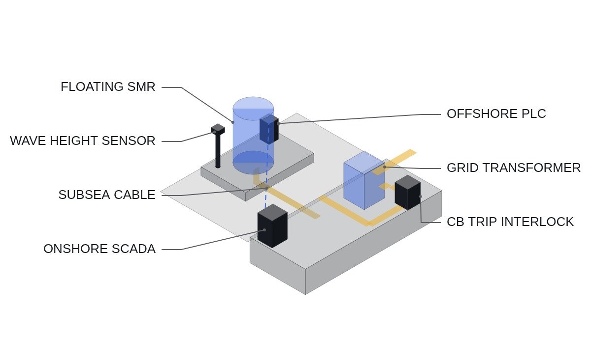
- [ ] Trip interlock for the circuit breaker (CB) at the land-sea grid connection point — trip within 200 ms when frequency deviation exceeds ±0.5 Hz (I/O: DI_FREQ_DEV, DO_CB_TRIP)
- [ ] Continuous monitoring of submarine cable insulation resistance (IR) — alarm when IR < 1 MΩ, automatic disconnection circuit operates (I/O: AI_IR_CABLE, DO_ALARM_IR). Note that this automatic disconnection circuit is not a substitute for the EMO (emergency stop) and is treated as separate protective relaying logic
- [ ] BMS/PCS communication redundancy — switch to a backup wireless link when the main link (optical fibre) is lost, switchover within 5 seconds (I/O: DI_COMM_FAULT, DO_BACKUP_LINK)
- [ ] Offshore wave height and tilt sensor interlock — automatic derating of generator output when design wave height is exceeded (I/O: AI_WAVE_HEIGHT, AO_POWER_DERATE)
- [ ] Time synchronisation between onshore SCADA and offshore PLC (IEC 61850 SNTP) — keep error within 1 ms; raise a communication reliability alarm if exceeded
- [ ] EMO (emergency stop) circuit — keep it hardwired; do not replace it with software trip logic
Operating time chart (concept)
Because the preconditions for the drive sequence (actual platform vendor specifications) have not yet been published, the following is a conceptual time chart following the IEC 61513 baseline. It must be re-verified against vendor specifications in actual application.
T+0ms    Abnormality detected (AI_FREQ_DEV, AI_IR_CABLE threshold exceeded)
T+50ms   First alarm raised (DO_ALARM set)
T+100ms  Output derating starts (AO_POWER_DERATE ramps down)
T+200ms  DO_CB_TRIP set if CB trip conditions are met
T+5000ms Communication redundancy switchover confirmed (DI_COMM_FAULT cleared)
* The EMO circuit remains hardwired and on constant standby, independent of this sequence
Notes for practical application
The checklist itself is the list of action items. Until the ATLAS standard is finalised, however, the I/O addresses and timing values above are provisional values borrowed from the land-based SMR baseline, and each item must be re-verified against the actual floating platform vendor’s instrumentation and control specification. Figures related to submarine cable insulation degradation or communication noise must be confirmed through on-site waveform analysis and field measurement.
Frequently asked questions
Q. What is the IAEA ATLAS project?
It is a project for the international regulatory standardisation of floating nuclear power plants and nuclear-powered ships, for which the IAEA held a launch meeting on 25-26 August 2026. The actual grid connection specifications have not yet been published as standard documents.
Q. How does grid connection differ between land-based and floating SMRs?
Because the connection runs through a submarine cable, offshore-specific variables are added, such as changes in cable tension with wave height and insulation resistance degradation from seawater ingress. These values have to be confirmed by field measurement until the standard is finalised.
Q. Can the values in this checklist be applied as they are?
No. The I/O addresses and timing values are provisional values borrowed from the IEC 61513 land-based baseline, and each item must be re-verified against the actual platform vendor’s instrumentation and control specification.
Land-based vs floating SMR: grid connection character
Why the checklist items depart from the land-based baseline becomes clear when the two connection structures are set side by side. The table compares equipment character only, not values.
| Item | Land-based SMR | Floating SMR |
|---|---|---|
| Connection path | Direct to onshore lines and substation | Via submarine cable to an onshore connection point |
| Insulation degradation drivers | Ordinary outdoor environment | Seawater ingress, cable tension changes with wave height |
| Protection and control signal path | Wiring within one site | Onshore SCADA and offshore PLC separated by a remote link |
| Output constraints | Mainly grid conditions | Grid conditions plus offshore weather and platform tilt |
| Standard status | IEC 61513 / IEC 61850 framework applies | ATLAS at launch stage, connection specs unpublished |
Implication: on a floating SMR the grid-side circuit breaker (CB) sits onshore while reactor-side output control sits offshore, so the two protective actions are linked by a submarine communication path rather than by wiring on one site; the centre of interlock design moves from protecting a single installation to the reliability of signals between two separated locations.
One practical criterion follows from this. Loss of the land-sea link should be treated as an abnormal signal in its own right, not as a mere communication fault alarm. If each location simply holds “the last healthy state it received” when the other side goes silent, operation continues without distinguishing a real abnormality from a lost link. The principle is that on signal loss each side falls to its own safe default: CB trip readiness onshore, output derating offshore. This default behaviour does not replace the hardwired EMO circuit either.
Boundary conditions: when this checklist does not fit
The checklist above rests on the premise that the floating platform is connected to the onshore grid by submarine cable. If ATLAS settles on supplying the vessel’s own loads or a dedicated off-grid consumer as the basic concept, the connection-point CB trip interlock and onshore SCADA time synchronisation items drop sharply in priority, and an offshore load-shedding sequence becomes the core instead. If the platform vendor presents protective relaying and reactor protection as one integrated specification, the item-by-item I/O split has to be redrawn against that specification. Judgements on insulation resistance and communication noise require waveform analysis and field measurement in either case. The criterion is one question: are both the onshore and offshore sides configured to act safely on their own when the submarine link is lost?
References: IAEA ATLAS project launch meeting (2026-08-25 to 26); Money Today, “Doosan Enerbility wins order for core TerraPower SMR components” (2026-08-14); IEC 61513 / IEC 61850 standards