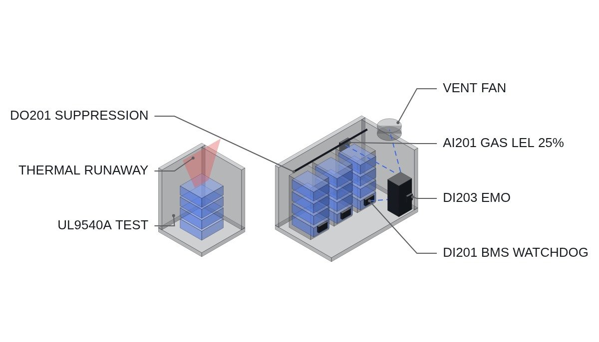
The conclusion first. Even an ESS that has already passed UL9540A Level 4 certification must separately meet the installation requirements of NFPA 855 (2026 edition). The two do not replace each other: one is certification (a product-level fire propagation test) and the other is installation (system-level separation distances, ventilation and interlock design). If the interlock designer misses this distinction, the result is a project that holds a certificate but gets stuck in site permitting.
UL9540A is a test the cell passes; NFPA 855 is a standard the installation passes.
The National Fire Protection Association (NFPA) has officially released the 2026 edition of “NFPA 855, Standard for the Installation of Stationary Energy Storage Systems,” fundamentally shifting the direction of its safety requirements. Where the previous 2023 edition focused on response and damage mitigation after a fire, the 2026 edition centers on a performance criterion: thermal runaway itself must not propagate to adjacent cells and modules. The key point of this revision is that it defines fire causes to include not only battery cells but also the complex interactions with the BOS (Balance of System), such as wiring, cooling and HVAC systems, and the BMS. In Korea, applications to enact or revise the fire safety technical standards (NFTC) have been filed in response to these changes in international standards.
Precondition: no information has been provided on the exact permitting procedure for any individual site, so the checklist below is developed for a typical ESS configuration in which UL9540A Level 4 certified battery units are combined with a BOS and installed outdoors. In actual application, it must be replaced and confirmed against the procedures of the competent fire authority and the equipment manufacturer’s specifications.
Safety interlock check order (top priority)
- EMO (emergency off) — the principle is a hardware-wired configuration that directly cuts the charge/discharge gate; designs that replace or bypass the EMO function with software logic alone are not covered on this site.
- Gas detection (H2/CO) interlock — when the lower explosive limit (LEL) exceeds 25%, start the ventilation fan and cut the charge/discharge gate at the same time
- BMS communication watchdog interlock — cut immediately to fail-safe on communication loss (prevents a BOS-level fault from turning into a misjudgment of cell state)
- Cooling fan and pump running-status interlock — alarm and de-rating when a stop is detected, cut-off if it persists
- Fire suppression interlock — when fire detection is confirmed, start the automatic suppression system at the same time as cutting the PCS gate
BOS interlock checklist (I/O map)
| Signal | I/O address | Type | Operating condition |
|---|---|---|---|
| EMO pressed status | DI203 | Digital In (hardwired) | 1 = pressed → cannot be bypassed by the PLC; gate cut directly |
| Gas detection (H2/CO) | AI201 | Analog In 4-20mA | Above LEL 25%: start ventilation fan + cut-off |
| BMS communication watchdog | DI201 | Digital In | Communication loss over 500ms: fail-safe cut-off |
| Cooling fan/pump status | DI202 | Digital In | 0 = stopped → alarm; if it persists, de-rating or cut-off |
| Fire suppression start signal | DO201 | Digital Out | Outputs 1 when fire detection is confirmed |
The implication of this checklist is clear. A UL9540A Level 4 test report does not guarantee the field wiring and maintenance condition of BOS interlocks such as DI201, AI201 and DI202, so NFPA 855 installation requirements must be rechecked at every site, separately from the certificate.
PLC logic snippet (IEC 61131-3 Structured Text pseudocode)
(* ESS BOS interlock - fail-safe based on BMS watchdog *)
(* DI201: BMS communication watchdog, AI201: gas concentration (LEL%), DI202: cooling fan status *)
IF DI201 = 0 THEN
    DO_CHARGE_GATE_ENABLE := FALSE; (* communication loss over 500ms, fail-safe cut-off *)
ELSIF AI201 > 25.0 THEN
    DO_VENT_FAN := TRUE;
    DO_CHARGE_GATE_ENABLE := FALSE; (* above LEL 25%, ventilation + cut-off together *)
ELSIF DI202 = 0 THEN
    DO_CHARGE_GATE_ENABLE := FALSE; (* cooling stop persists, cut-off after de-rating *)
ELSE
    DO_CHARGE_GATE_ENABLE := TRUE;
END_IF;
Boundary conditions — handling field variables
When and how NFPA 855 (2026 edition) will be reflected in Korea’s KS and NFTC, and the detailed clauses, have not yet been formally announced, so the specific scope of application to domestic installation sites must be confirmed with the competent fire authority alongside field measurement — requires waveform analysis and field measurement. Whether it will apply retroactively to facilities completed with UL9540A Level 4 certification alone is also unclear at present. The selection criterion comes down to one question: are the certificate (test report) and the installation interlocks (BOS I/O map) managed as separate documents?
References
- E2News, “2026 edition of ‘NFPA 855’ significantly tightens ESS safety standards… thermal runaway propagation prevention is the key”
- Energy Newspaper, “Seminar on response strategies for the revised ‘NFPA 855’ ESS installation standard to be held”
- US7433794B1 — Tesla Motors, Mitigation of propagation of thermal runaway in a multi-cell battery pack (Google Patents)