To state the conclusion first: the rear-side gain of a bifacial module is created not by the module spec but by the ground reflectance at the site, mounting height, row spacing, and whatever structure shades the rear side. Over bright roof membranes, white gravel, snow-covered ground, or high racking the gain is large; over dark soil or grass, low racking, or dense layouts it is small. There is also an easy-to-miss electrical point. String current rises by the amount of the rear gain, so inverter input current, cable, and fuse margins sized on front irradiance alone may fall short.
Where It Wins, Where It Doesn’t
Under current conditions, a monofacial module converts only light entering from the front. The back is sealed by a backsheet, and light reflected from the ground is simply lost. The designer only has to manage azimuth, tilt, and shading.
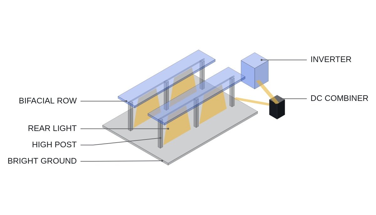
With bifacial modules, ground-reflected light and part of the diffuse sky light enter from the rear and produce additional current. From that point on, the ground becomes part of the plant. The brighter the ground, the higher the module sits above it, and the wider the rows so more light reaches the ground, the higher the rear irradiance.
The connecting logic is this. A bifacial module becomes different equipment depending on which ground it sits over. The question “is bifacial better?” should therefore be recast from a module comparison into a site comparison, and the data needed is not the module datasheet but ground reflectance and racking geometry.
A Framework for the Rear-Side Gain
Effective irradiance on a bifacial module is approximated as G_eff = G_front + φ × G_rear, where φ is the bifaciality factor, the ratio of rear efficiency to front efficiency, given on the module datasheet. The method for measuring current-voltage characteristics of bifacial devices is covered by IEC TS 60904-1-2.
A worked example with assumed values. Assumption: G_front = 1,000 W/m², G_rear = 100 W/m², φ = 0.7. Then G_eff = 1,000 + 0.7 × 100 = 1,070 W/m², and since short-circuit current is nearly proportional to irradiance, current rises by about 7%. Voltage is insensitive to irradiance changes, so most of the power increase shows up as current.
G_rear is not a fixed value. Even on the same site the ground changes with the seasons, rear irradiance differs between the bottom and top edges of a module, and the racking casts shadows on the rear. Simulated values should therefore be tracked at design stage and rear pyranometer measurements at operating stage, separately.
| Ground condition | Rear gain | Notes |
|---|---|---|
| White roof membrane | Large | Reflectance drops when soiled |
| Light gravel or concrete | Medium to large | Can be maintained by ground upkeep |
| Snowy regions | Seasonally large | Limited to snow season |
| Grass or dark soil | Small | Vegetation control needed |
| Water (floating PV) | Small | Little reflection at high sun angles |
| Low racking, dense rows | Small | Rear shaded even over bright ground |
The last row is the one most often overlooked. However bright the ground, if modules sit low and rows are tight, light has no path to the rear. Reflectance and geometry act as a product, so if either is small, the gain is small.
What Changes in Electrical Design
Because the rear gain appears as current, DC-side current ratings must be revisited. If string fuses, DC cable ampacity, combiner breakers, and the inverter’s MPPT input current limit are all sized on front-irradiance short-circuit current, margin shrinks by the rear contribution. The design current must be stated with the rear contribution included.
Above the inverter’s input current limit, the inverter shifts its operating point and limits output, so part of the rear gain is cut at the inverter. In designs with a high DC/AC ratio, the inverter already hits its rating at midday, so there are more hours in which the rear gain does not translate into extra energy.
Uneven rear irradiance also becomes an electrical loss. Edge rows of an array receive more ground-reflected light and middle rows less, and within a row, cells directly behind posts or a torque tube fall into shade. The current of a series string settles to that of the least-irradiated module, so uneven rear irradiance turns part of the theoretical gain into mismatch loss. The size of that loss varies with layout and must be confirmed by measurement.
The performance evaluation method also needs to be fixed. If the performance ratio (PR) is calculated with front irradiance only, the rear gain enters only the numerator and PR comes out higher than reality. If a performance guarantee or O&M contract does not state whether reference irradiance is front-only or includes the rear contribution, equipment faults can hide behind a good-looking PR.
| Check item | Monofacial basis | Extra for bifacial |
|---|---|---|
| Design current | Front Isc | State conditions incl. rear contribution |
| Inverter input | MPPT current limit | Check hours above the limit |
| DC/AC ratio | Midday clipping review | Include lost rear gain |
| Monitoring | Front pyranometer | Add rear pyranometer |
The core of this table is that the rear gain is a current-rating issue before it is an energy-yield issue. Before calculating the extra energy, confirm that the DC circuit can carry the increased current.
Vertical Mounting as a Different Answer
Mount bifacial modules vertically facing east and west, and the front catches the morning sun while the rear catches the afternoon sun. The output curve gets two peaks, morning and afternoon, instead of one at midday. On total energy alone this can lose to a south-facing tilted array, but on grids where midday curtailment applies or midday power is worth little, the generating hours themselves become the value.
Vertical mounting leaves the ground between rows open, so it also fits side conditions such as agrivoltaics, dual use as fencing, and less snow accumulation. In that case the reason for choosing bifacial is not the rear gain but the shape of the output curve.
Decision Sequence
- Confirm the reflective characteristics of the ground at the site and their seasonal changes (snow, vegetation, soiling).
- Set racking height and row spacing, and simulate rear irradiance.
- Review fuse, cable, and inverter input ratings against a design current that includes the rear contribution.
- Recalculate the actual extra energy with the DC/AC ratio and curtailment conditions applied.
- In operation, measure with a rear pyranometer and track the gap against simulation.
Boundary Conditions
The bifacial advantage flips when the ground is dark and the racking is low. The rear gain is then small, and only the extra burden of current-rating margin and monitoring remains. In designs with a high inverter loading ratio and frequent midday clipping, much of the rear gain also fails to become energy. Conversely, where the module price difference is negligible, the criterion shifts from the size of the gain to whether the electrical design burden increases.
The single decision criterion is this: choose bifacial only when the ground at the site is bright, the modules sit high enough above it for the rear to receive light, and the DC circuit can carry the increased current.