Unlike an ESS battery, an electrolyzer system is a rectifier load that draws power from the grid and converts it via a chemical reaction (water electrolysis). Taking as a starting point a demonstrated 10 MW-class electrolyzer system Toyota installed at its Aichi Prefecture head-office plant, this article organizes the Safety Interlock check order and I/O checklist that must be confirmed first when interconnecting a PCS/rectifier to the grid. Starting with the conclusion: the interlock priority for an electrolyzer system must be designed differently from a standard ESS PCS — the hydrogen-concentration interlock must always rank above the electrical grid interlock.
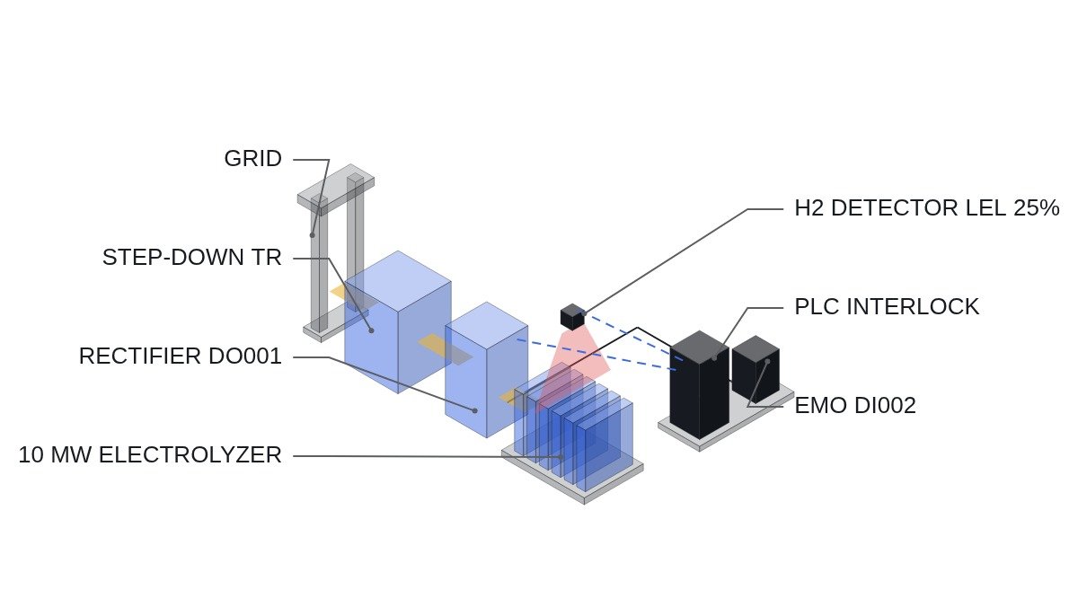
Precondition: since exact operating-sequence information for the individual site was not provided, the checklist below is developed based on the general startup time chart of an alkaline/PEM electrolyzer stack. Before actual application, this must always be replaced and confirmed against the stack manufacturer’s specification-based time chart.
Safety Interlock Check Order (Highest Priority)
- Hydrogen concentration interlock — gas detector signal; rectifier gate trips immediately upon reaching 25% of the Lower Explosive Limit (LEL)
- Stack temperature/pressure interlock — de-rating followed by shutdown upon exceeding rated values
- Grid-side electrical interlock — undervoltage (UVR)/overvoltage (OVR)/frequency abnormality/anti-islanding detection
- EMO (Emergency Off) — the principle is a configuration that directly trips the rectifier gate signal via hardwired circuitry; a design that substitutes or bypasses the EMO function with software logic alone is not covered on this site.
Grid-Interconnection Startup Sequence Checklist (I/O Map)
| Signal Name | I/O Address | Type | Operating Condition |
|---|---|---|---|
| Hydrogen detector LEL signal | DI001 | Digital In | 0=normal, 1=alarm (LEL ≥25%) → immediate gate trip |
| EMO pressed state | DI002 | Digital In (hardwired) | 1=pressed → PLC bypass not possible, rectifier tripped directly |
| Grid voltage normal | DI003 | Digital In | UVR/OVR relay output, 0=abnormal |
| Rectifier gate enable | DO001 | Digital Out | Outputs 1 only when all interlocks are normal |
| Stack current | AI001 | Analog In 4-20mA | 0-4000A, de-rating upon exceeding rated value |
| Stack temperature | AI002 | Analog In 4-20mA | 0-90℃, alarm at ≥80℃ |
This checklist itself constitutes the practical execution items. In particular, DI001 (hydrogen detection) and DI002 (EMO) must carry hardware priority independent of the PLC scan cycle, and a configuration that relies solely on software interlock logic is not recommended under this site’s safety-narrative principle.
PLC Logic Snippet (IEC 61131-3 Structured Text Pseudocode)
(* Electrolyzer grid-interconnection gate enable logic *)
(* DI001: H2 LEL alarm, DI002: EMO hardwired, DI003: grid voltage normal *)
IF DI001 = 1 THEN
    DO001 := FALSE; (* Highest-priority trip on hydrogen alarm, ms-scale response required *)
ELSIF DI002 = 1 THEN
    DO001 := FALSE; (* EMO is tripped directly via hardware in principle; this line is for status display only *)
ELSIF DI003 = 0 THEN
    DO001 := FALSE; (* Grid voltage abnormal *)
ELSIF AI002 > 800 THEN (* 80.0℃, 0.1℃ resolution *)
    DO001 := FALSE; (* Stack overtemperature *)
ELSE
    DO001 := TRUE; (* Gate enabled only when all conditions are normal *)
END_IF;
Boundary Condition — Response to Field Variables
A case where the grid-side anti-islanding detection signal intermittently malfunctions, or the DI003 signal momentarily flickers, may indicate noise ingress in the PCS communication protocol (Modbus/CAN) section. Since grounding conditions and cable routing paths differ by site, this cannot be uniformly concluded, and is left pending as requiring waveform analysis and field measurement. Adjusting only the interlock threshold without identifying the root cause is not recommended.
References
- Monthly Hydrogen Economy, Toyota’s 3rd-generation fuel cell and 10MW electrolyzer system demonstration in Aichi Prefecture (Korean)
- WO2023104267A1, Electrolyser system and method of its operation for supporting stability of a power grid
- Gas Newspaper, 2026 Green Hydrogen and Fuel Cell Market Outlook (Korean)