With Doosan Enerbility signing a contract with TerraPower to manufacture equipment for a sodium-cooled SMR, Korean supply-chain participation is now under way in earnest. This article does not cover mechanical structural design such as the reactor guard vessel or support structures (outside this site’s scope). Instead, from an electrical engineer’s point of view, it sets out how the protection system trip logic and instrumentation signal architecture of a sodium-cooled fast reactor (SFR) differ from those of a light water reactor (LWR). Conclusion: an SFR relies heavily on a passive decay heat removal system (PDRC) that keeps working by natural convection even when electrical signals are lost, so the interlock design philosophy itself shifts from “the electrical trip succeeds” to “the plant stays on the safe side even when electrical signals are lost.”
Premise: detailed design values for any specific project are not public, so this article works from the generally known principles of SFR passive safety systems. For any actual application, these must be replaced and verified against a time chart based on the final safety analysis report (FSAR) for the reactor type in question.
Safety interlock verification order (top priority)
- Sodium leak detection interlock — signals from temperature-type and acoustic leak detectors; sodium reacts violently with water, so this ranks first
- Core temperature and neutron flux interlock — control rod insertion trip when ratings are exceeded
- Cover gas (inert gas) pressure interlock — alarm to inspect the sealing system on abnormal pressure
- EMO (Emergency Off) — the principle is a hardware-wired configuration that drives the trip circuit directly; designs that replace or bypass EMO with software alone are not covered here.
LWR vs sodium-cooled SMR: trip logic difference checklist
| Item | Light water reactor (LWR) | Sodium-cooled SMR (SFR) |
|---|---|---|
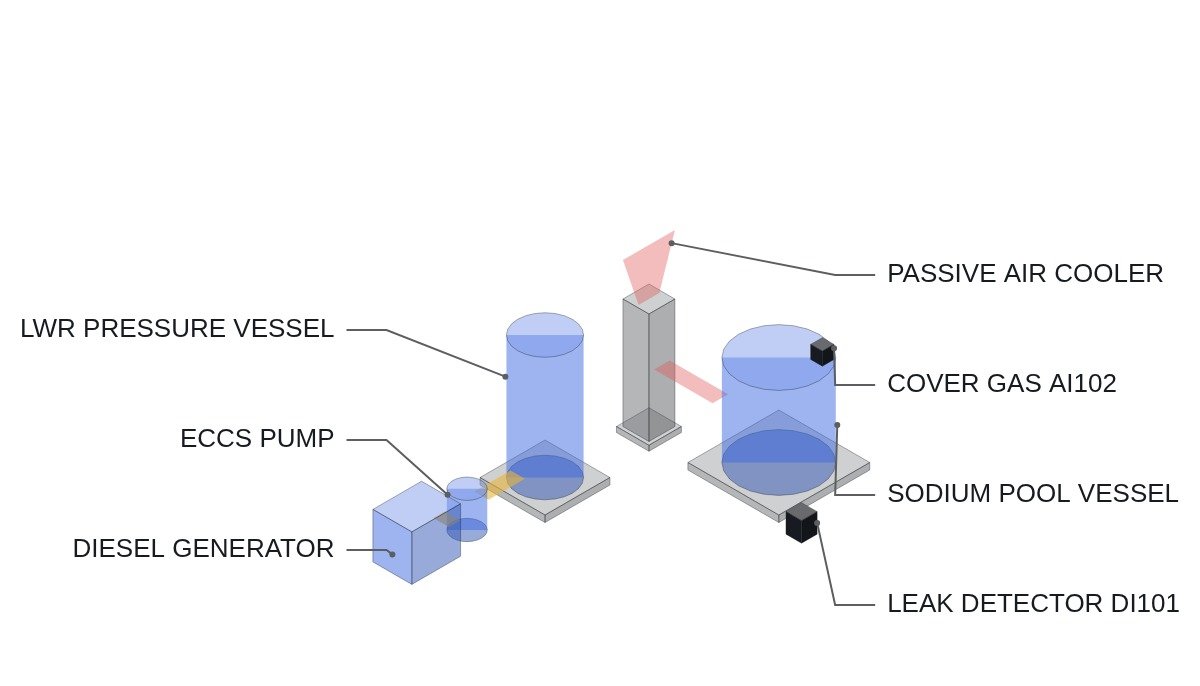
| Decay heat removal | Emergency core cooling system (ECCS), heavy reliance on active pump drive | Passive decay heat removal (PDRC), heavy reliance on natural convection |
| On loss of electrical signals | Risk of losing cooling if emergency diesel generators fail to start | Decay heat removal continues by natural convection without electrical signals |
| Additional interlock signals | Core water level, containment pressure | Sodium leak detection, cover gas pressure |
| Main instrumentation | Differential-pressure level gauges | Ultrasonic sodium level gauges, thermocouples |
| Fire and reactivity risk | Hydrogen generation (zirconium-water reaction) | Sodium-water/air reaction |
Instrumentation I/O map (example)
| Signal | I/O address | Type | Operating condition |
|---|---|---|---|
| Sodium leak detection (temperature-type) | DI101 | Digital In | 1 = detected → immediate trip alarm, isolate downstream systems |
| EMO pressed status | DI102 | Digital In (hardwired) | 1 = pressed → directly drives control rod insertion circuit |
| Core outlet temperature | AI101 | Analog In (thermocouple) | 0–650 ℃, de-rating when upper limit exceeded |
| Cover gas pressure | AI102 | Analog In | Alarm on ±10% deviation from rating |
| Sodium level (ultrasonic) | AI103 | Analog In | Pump trip interlock on low-limit deviation |
Protection system logic snippet (IEC 61131-3 Structured Text pseudocode)
(* Example SFR core protection trip logic - for concept explanation only, not a substitute for the actual FSAR *)
(* DI101: sodium leak detection, DI102: EMO hardwired, AI101: core outlet temperature *)
IF DI101 = 1 THEN
    TRIP_SIGNAL := TRUE; (* sodium leak is the top-priority trip, ms-level response required *)
ELSIF DI102 = 1 THEN
    TRIP_SIGNAL := TRUE; (* EMO is driven directly in hardware; this line is for status display *)
ELSIF AI101 > 6500 THEN (* 650.0 C, 0.1 C resolution *)
    TRIP_SIGNAL := TRUE;
ELSE
    TRIP_SIGNAL := FALSE; (* PDRC remains on standby at all times even when no trip is active *)
END_IF;
Boundary conditions: dealing with field variables
Sodium leak detection signals vary widely in field measurements depending on sensor placement and piping medium conditions at each site, so it is difficult to generalize and present a specific threshold. Whether temperature-type detectors show response delay or acoustic detectors suffer background noise interference is held open: it requires waveform analysis and field measurement. Evaluating the mechanical durability of structures is outside this site’s scope, so this article limits the discussion to electrical protection system logic and the instrumentation signal architecture.
References
- Global Economic, Doosan Enerbility and TerraPower sign contract to manufacture key equipment for sodium reactor
- US8670518B2, Fully passive decay heat removal system for sodium-cooled fast reactors
- Hankyung Magazine, SMRs emerge as a relief pitcher for the AI power crunch